Chapter 8
8-30
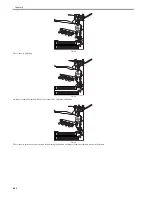
F-8-44
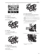
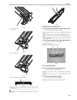
An image is formed for the 1st side of the 5th sheet.
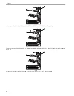
F-8-45
The 5th sheet is delivered.
8.10 Delivery
8.10.1 Delivery Control
0014-3198
/ / / / iR C3380i / iR C3380 / iR C2880i / iR C2880
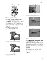
There are some delivery accessories available for this machine: the 2 / 3 delivery units, the finisher Z1 and the saddle finisher Y2. For the purpose of improving the
productivity, the 2 / 3 delivery units are connected to the main body as the standard equipments. Also, when mounting the finisher Y1or the saddle finisher Y2,
buffer path unit must be mounted.
8.10.2 Delivery to the Main Body Tray
0014-3207
/ / / / iR C3380i / iR C3380 / iR C2880i / iR C2880
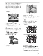
In case media is delivered to the delivery outlet 1, the processing speed is accelerated when the trailing edge of media reaches the point of fixing rear 10
mm. Due to the drive configuration of the delivery motor 1, when the motor is rotating at 1/2 speed or slower, feeding speed cannot be accelerated to 1/2 speed or
faster. For this reason, the feeding speed is not accelerated when the processing speed is 1/2 speed. When the processing speed is 1/4, the feeding speed is accelerated
to 1/2 speed (71.5 mm/s). When the feeding speed of the media is accelerated to 337 mm/s and the media is delivered from the delivery outlet 1, for the purpose of
keeping consistency in its speed, the feeding speed is decelerated so that the feeding speed returns to constant speed when the trailing edge (5mm) reaches the fixing
rear roller.
When media is delivered to the delivery outlet 1 and 2, the feeding speed is accelerated at the point of inner delivery 10mm. When the processing speed is
constant, the feeding speed is accelerated to 460mm/s. Due to the drive configuration of the delivery motor 2 and 3, when the motor is rotating at 1/2 speed or slower,
feeding speed cannot be accelerated to 1/2 speed or faster. For this reason, the feeding speed is not accelerated when the processing speed is 1/2 speed. When the
processing speed is 1/4, the feeding speed is accelerated to 1/2 speed (71.5 mm/s). When the feeding speed of the media is accelerated to 460 mm/s and the media
is delivered from the delivery outlet 2, for the purpose of keeping consistency in its speed, the feeding speed is decelerated so that the feeding speed returns to
constant speed when the trailing edge (5mm) reaches the fixing rear roller.
When the media is delivered to the delivery outlet 3, the media stops temporarily after acceleration at the reversal slot, and then is fed to the delivery outlet 3 at
460mm/s. In this case as well, for the purpose of keeping consistency in its speed, the feeding speed is decelerated so that the feeding speed returns to constant speed
when the trailing edge (5mm) reaches the fixing rear roller.
In this machine, the delivery method is FD (face-down) delivery only in delivery 1 through 3. There is no so-called "reversal delivery mechanism" in which switch-
over of FU (face-up) / FD (face-down) is available.
8.10.3 Delivery Operation when Mounting the Delivery Accessory
0014-3208
/ / / / iR C3380i / iR C3380 / iR C2880i / iR C2880
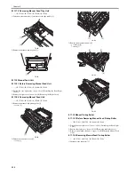
1. Delivery to the Finisher Z1
When the machine is mounted with the finisher Z1, due to the short path length until delivery, there occurs no acceleration during delivery if the image formation
is performed at constant speed or 1/2 speed. In the case of 1/4 speed, the feeding speed is accelerated to 1/2 speed when the trailing edge of the paper passes the
point 10 mm away after inner delivery roller.
5
5
4
1
2
3
4
1
2
3
5
Summary of Contents for iR C3380 series
Page 1: ...Aug 29 2006 Service Manual iR C3380 2880 Series...
Page 2: ......
Page 6: ......
Page 23: ...Chapter 1 Introduction...
Page 24: ......
Page 26: ......
Page 52: ......
Page 53: ...Chapter 2 Installation...
Page 54: ......
Page 127: ...Chapter 3 Basic Operation...
Page 128: ......
Page 130: ......
Page 136: ......
Page 137: ...Chapter 4 Main Controller...
Page 138: ......
Page 160: ......
Page 161: ...Chapter 5 Original Exposure System...
Page 162: ......
Page 188: ...Chapter 5 5 24 F 5 68 4 Remove the original sensor 2 hook 1 F 5 69...
Page 189: ...Chapter 6 Laser Exposure...
Page 190: ......
Page 192: ......
Page 206: ......
Page 207: ...Chapter 7 Image Formation...
Page 208: ......
Page 256: ......
Page 257: ...Chapter 8 Pickup Feeding System...
Page 258: ......
Page 262: ......
Page 303: ...Chapter 9 Fixing System...
Page 304: ......
Page 306: ......
Page 321: ...Chapter 10 Externals and Controls...
Page 322: ......
Page 326: ......
Page 336: ...Chapter 10 10 10 F 10 10 2 Remove the check mark from SNMP Status Enabled...
Page 337: ...Chapter 10 10 11 F 10 11...
Page 359: ...Chapter 11 MEAP...
Page 360: ......
Page 362: ......
Page 401: ...Chapter 12 RDS...
Page 402: ......
Page 404: ......
Page 411: ...Chapter 13 Maintenance and Inspection...
Page 412: ......
Page 414: ......
Page 416: ...Chapter 13 13 2 F 13 1 8 9 1 2 3 3 5 6 7 10 11 12 13 14 4...
Page 421: ...Chapter 14 Standards and Adjustments...
Page 422: ......
Page 424: ......
Page 431: ...Chapter 15 Correcting Faulty Images...
Page 432: ......
Page 434: ......
Page 459: ...Chapter 16 Self Diagnosis...
Page 460: ......
Page 462: ......
Page 481: ...Chapter 17 Service Mode...
Page 482: ......
Page 484: ......
Page 571: ...Chapter 18 Upgrading...
Page 572: ......
Page 574: ......
Page 603: ...Chapter 19 Service Tools...
Page 604: ......
Page 606: ......
Page 609: ...Aug 29 2006...
Page 610: ......


