Chapter 12
12-2
12.1.7 Resend at SOAP transmission error
0013-8737
/ / / / iR C3380i / iR C3380 / iR C2880i / iR C2880
When SOAP send error is generated by the trouble on UGW side etc. at the transmission of an alert code, the latest three batches of data that failed in the transmission
are stored in HDD, and e-RDS resends it at prescribed intervals.
12.1.8 e-RDS setting screen
0013-8738
/ / / / iR C3380i / iR C3380 / iR C2880i / iR C2880
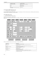
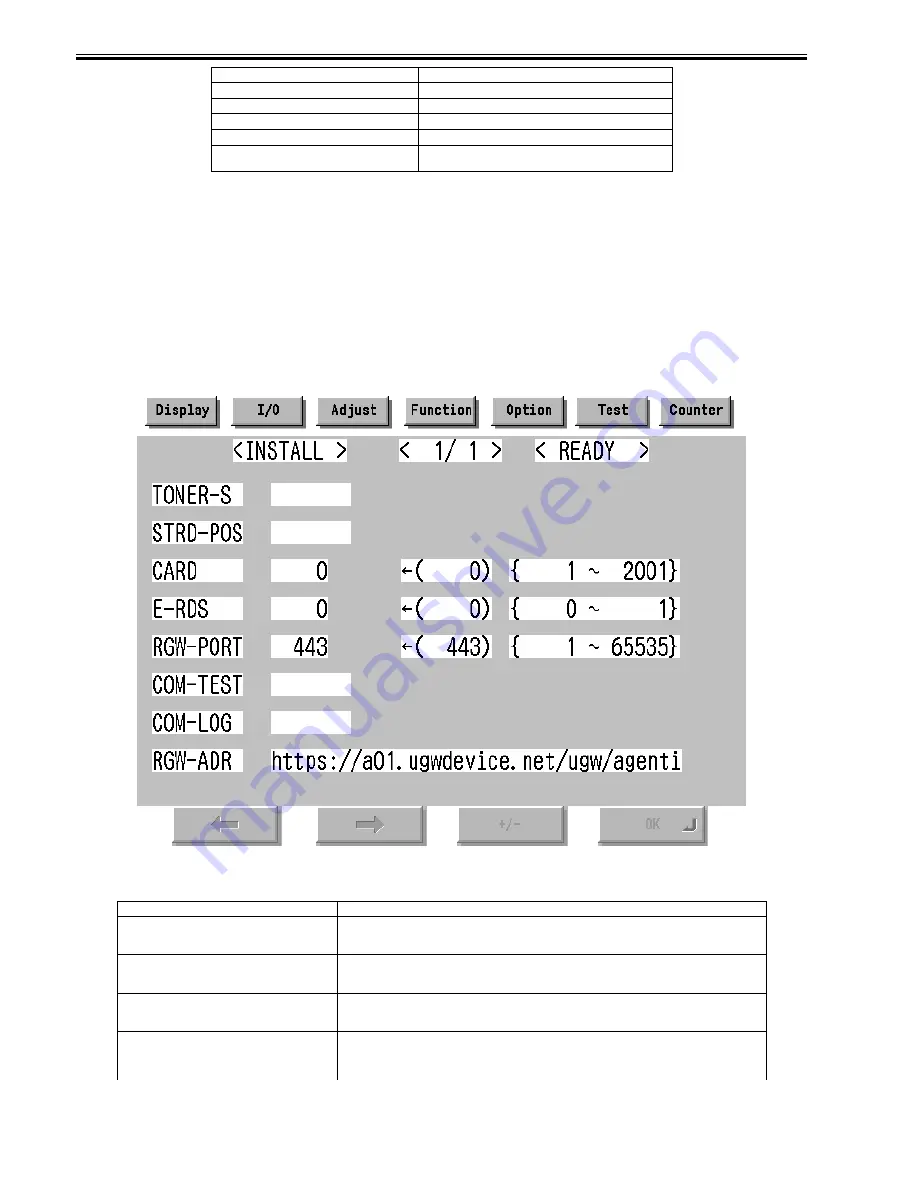
The e-RDS setting screen is in the service mode screen.
When the tab above is selected on any e-RDS setting screen, it changes to the mid item screen. Moreover, it returns to previous screen when reset key is pressed.
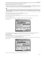
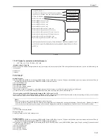
Menu Screen
F-12-1
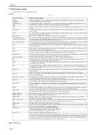
Setting screen of e-RDS. The form and the initial value of each setting item are as follows.
Transmission of alert code
When the state of the device is changed.
Jam
When Jam occurs
Alarm
When Alarm occurs
Error
When Error occurs
Confirmation whether there is processing that e-
RDS executes
Every 6 hours
Item(meaning)
Explanation
E-RDS
(Embedded-RDS)
Turning OFF/ON e-RDS. 0:OFF / 1:ON
Counter information and error information are transmitted to the host at ON.
Initial value: 0: OFF
RGW-ADR
(RDS-Gateway ADDRESS)
URL of the host (When the input area is selected (touched), shift to the keyboard screen)
Initial value: URL of an actual host.
Length: 129 characters (NULL is contained)
RGW-PORT
(RDS-Gateway PORT)
Port Number of the host
Initial value: 443
Range of available number: 1-65535
COM-TEST
(Communication Test)
Execution of Communication test
Communication test starts when you select (touch) this and press the [OK] key.
e-RDS tries the connection with the host, and displays the result by "OK!" or "NG!". (NG: No Good, the
communication test is failed)
Content of transmission
Transmission timing
Summary of Contents for iR C3380 series
Page 1: ...Aug 29 2006 Service Manual iR C3380 2880 Series...
Page 2: ......
Page 6: ......
Page 23: ...Chapter 1 Introduction...
Page 24: ......
Page 26: ......
Page 52: ......
Page 53: ...Chapter 2 Installation...
Page 54: ......
Page 127: ...Chapter 3 Basic Operation...
Page 128: ......
Page 130: ......
Page 136: ......
Page 137: ...Chapter 4 Main Controller...
Page 138: ......
Page 160: ......
Page 161: ...Chapter 5 Original Exposure System...
Page 162: ......
Page 188: ...Chapter 5 5 24 F 5 68 4 Remove the original sensor 2 hook 1 F 5 69...
Page 189: ...Chapter 6 Laser Exposure...
Page 190: ......
Page 192: ......
Page 206: ......
Page 207: ...Chapter 7 Image Formation...
Page 208: ......
Page 256: ......
Page 257: ...Chapter 8 Pickup Feeding System...
Page 258: ......
Page 262: ......
Page 303: ...Chapter 9 Fixing System...
Page 304: ......
Page 306: ......
Page 321: ...Chapter 10 Externals and Controls...
Page 322: ......
Page 326: ......
Page 336: ...Chapter 10 10 10 F 10 10 2 Remove the check mark from SNMP Status Enabled...
Page 337: ...Chapter 10 10 11 F 10 11...
Page 359: ...Chapter 11 MEAP...
Page 360: ......
Page 362: ......
Page 401: ...Chapter 12 RDS...
Page 402: ......
Page 404: ......
Page 411: ...Chapter 13 Maintenance and Inspection...
Page 412: ......
Page 414: ......
Page 416: ...Chapter 13 13 2 F 13 1 8 9 1 2 3 3 5 6 7 10 11 12 13 14 4...
Page 421: ...Chapter 14 Standards and Adjustments...
Page 422: ......
Page 424: ......
Page 431: ...Chapter 15 Correcting Faulty Images...
Page 432: ......
Page 434: ......
Page 459: ...Chapter 16 Self Diagnosis...
Page 460: ......
Page 462: ......
Page 481: ...Chapter 17 Service Mode...
Page 482: ......
Page 484: ......
Page 571: ...Chapter 18 Upgrading...
Page 572: ......
Page 574: ......
Page 603: ...Chapter 19 Service Tools...
Page 604: ......
Page 606: ......
Page 609: ...Aug 29 2006...
Page 610: ......


