Chapter 16
16-6
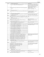
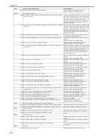
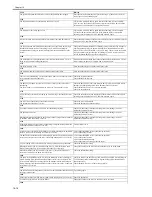
*** 0001 The HP sensor fails to be ON within 2000ms after the front adjuster plate starts to move
to its HP.
Replace the front adjuster plate HP sensor (SR3) ,
Replace the front adjuster plate motor (M3) , Replace
the adjuster plate drive belt
*** 0002 The HP sensor fails to be OFF within 1000ms after the front adjuster plate starts to move
from its HP.
**** 0001 The HP sensor fails to be OFF after the swing motor rotates for a specific period of time. Replace the rear adjuster plate HP sensor (PI37) ,
Replace the rear adjuster plate motor (M34)
**** 0002 The HP sensor fails to be ON after the swing motor rotates for a specific period of time.
E540
*** Stack tray up/down error / **** Upper tray up/down error
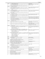
*** 0002 Paper surface detection fails to end within 1000ms.
Replace the stack tray top paper sensor (SR9) , Replace
the stack tray bottom paper sensor (SR10) , Replace the
stack tray upper limit sensor (SR13) , Replace the stack
tray lower limit sensor (SR12) , Replace the stack tray
shift motor (M7)
*** 0003 Encoder lock within 200ms fails to reach 10pulse during paper surface detection.
*** 0004 Outputs of the top paper sensor, bottom paper sensor, tray upper limit sensor, and tray
lower limit sensor have abnormality during paper surface detection.
**** 0001 The upper tray up/down motor clock is abnormal.
Replace the shift motor (M37) of the tray 1, Replace
the shift area sensor PCB of the tray 1
**** 0002 Area is abnormal.
**** 0003 The safety switch is activated.
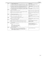
E542 ****
Lower tray up/down error
0001 The lower tray up/down motor clock is abnormal.
Replace the shift motor (M38) of the tray 2, Replace
the shift area sensor PCB of the tray 2
0002 Area is abnormal.
0003 The safety switch is activated.
E577 ***
Paddle error
0001 The HP sensor fails to be ON within 1500ms after the paper retaining paddle starts to
move to its HP.
Replace the paddle HP sensor (SR8) , Replace the
paddle motor (M6)
0002 The HP sensor fails to be OFF within 1000ms after the paper retaining paddle starts to
move from its HP.
E580
Stack tray up/down error
0001 The stack tray fails to reach the stack tray height sensor 4sec. after the stack tray up/
down motor starts to move up the tray; or the stack tray fails to come out of the height
sensor.
Check on overload on the stack tray up/down motor,
Replace the stack tray up/down motor (M5), Replace
the stack tray paper height sensor (S10) , Replace the
stack tray up/down motor clock sensor (S9)
E584 ****
Shutter unit error
0001 The shutter open sensor fails to be OFF (The shutter cannot be closed).
Replace the stack ejection motor (M32) , Replace the
shutter open/close clutch (CL31), Replace the shutter
HP sensor (PI45)
0002 The shutter open sensor fails to be ON (The shutter cannot be opened).
Replace the stack ejection motor (M32) , Replace the
shutter open/close clutch (CL31), Replace the shutter
HP sensor (PI45)
E590 *****
Puncher motor error
0001 The puncher HP sensor fails to be detected after the puncher motor is driven for 200ms. Replace the puncher HP sensor, Replace the puncher
motor
0002 The puncher fails to detect the puncher HP sensor after the puncher motor stops during
initial operation.
E591 *****
Puncher dust sensor error
0001 Light receiving voltage at the time of light emission is abnormal.
Replace the puncher dust sensor
0002 Light receiving voltage at the time of non-light-emission is abnormal.
E592 *****
Puncher side registration sensor error
0001 Light receiving voltage at the time of light emission is abnormal.
Replace the end sensor
0002 Light receiving voltage at the time of non-light-emission is abnormal.
0003 Light receiving voltage at the time of light emission is abnormal.
Replace the side registration sensor 1
0004 Light receiving voltage at the time of non-light-emission is abnormal.
0005 Light receiving voltage at the time of light emission is abnormal.
Replace the side registration sensor 2
0006 Light receiving voltage at the time of non-light-emission is abnormal.
0007 Light receiving voltage at the time of light emission is abnormal.
Replace the side registration sensor 3
0008 Light receiving voltage at the time of non-light-emission is abnormal.
0009 Light receiving voltage at the time of light emission is abnormal.
Replace the side registration sensor 4
000A Light receiving voltage at the time of non-light-emission is abnormal.
E593 *****
Puncher shift motor error
0001 The HP sensor fails to be OFF.
Replace the HP sensor, Replace the puncher shift
motor
0002 The HP sensor fails to be ON.
E5F0 ****
Saddle paper positioning error
0001 The paper positioning plate HP sensor fails to be ON after the paper positioning plate
motor is driven for 1.33 sec.
Replace the paper positioning plate motor (M4S),
Replace the paper positioning plate HP sensor (PI7S)
0002 The paper positioning plate HP sensor fails to be OFF after the paper positioning plate
motor is driven for 1 sec.
E5F1 ****
Saddle paper folder error
0001 The number of detection pulses for the paper folder motor clock sensor is below the
specific level.
Replace the paper folder motor (M2S), Replace the
paper folder motor clock sensor (PI4S)
0002 The paper folder HP sensor fails to change after the paper folder motor is driven for 3
sec.
E5F2 ****
Saddle guide error
0001 The guide HP sensor fails to be ON after the guide motor is driven for 0.455 sec.
Replace the guide motor (M3S), Replace the guide HP
sensor (PI13S)
0002 The HP sensor fails to be OFF after the guide motor is driven for 1 sec.
E5F3 ****
Saddle alignment error
Code
Main Cause/Detail of Detection
Countermeasures
Summary of Contents for iR C3380 series
Page 1: ...Aug 29 2006 Service Manual iR C3380 2880 Series...
Page 2: ......
Page 6: ......
Page 23: ...Chapter 1 Introduction...
Page 24: ......
Page 26: ......
Page 52: ......
Page 53: ...Chapter 2 Installation...
Page 54: ......
Page 127: ...Chapter 3 Basic Operation...
Page 128: ......
Page 130: ......
Page 136: ......
Page 137: ...Chapter 4 Main Controller...
Page 138: ......
Page 160: ......
Page 161: ...Chapter 5 Original Exposure System...
Page 162: ......
Page 188: ...Chapter 5 5 24 F 5 68 4 Remove the original sensor 2 hook 1 F 5 69...
Page 189: ...Chapter 6 Laser Exposure...
Page 190: ......
Page 192: ......
Page 206: ......
Page 207: ...Chapter 7 Image Formation...
Page 208: ......
Page 256: ......
Page 257: ...Chapter 8 Pickup Feeding System...
Page 258: ......
Page 262: ......
Page 303: ...Chapter 9 Fixing System...
Page 304: ......
Page 306: ......
Page 321: ...Chapter 10 Externals and Controls...
Page 322: ......
Page 326: ......
Page 336: ...Chapter 10 10 10 F 10 10 2 Remove the check mark from SNMP Status Enabled...
Page 337: ...Chapter 10 10 11 F 10 11...
Page 359: ...Chapter 11 MEAP...
Page 360: ......
Page 362: ......
Page 401: ...Chapter 12 RDS...
Page 402: ......
Page 404: ......
Page 411: ...Chapter 13 Maintenance and Inspection...
Page 412: ......
Page 414: ......
Page 416: ...Chapter 13 13 2 F 13 1 8 9 1 2 3 3 5 6 7 10 11 12 13 14 4...
Page 421: ...Chapter 14 Standards and Adjustments...
Page 422: ......
Page 424: ......
Page 431: ...Chapter 15 Correcting Faulty Images...
Page 432: ......
Page 434: ......
Page 459: ...Chapter 16 Self Diagnosis...
Page 460: ......
Page 462: ......
Page 481: ...Chapter 17 Service Mode...
Page 482: ......
Page 484: ......
Page 571: ...Chapter 18 Upgrading...
Page 572: ......
Page 574: ......
Page 603: ...Chapter 19 Service Tools...
Page 604: ......
Page 606: ......
Page 609: ...Aug 29 2006...
Page 610: ......

