Chapter 16
16-8
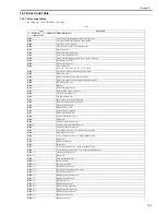
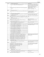
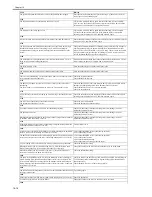
0401 Error is detected during encrypting.
Turn OFF and back ON the main power, Replace the
encryption board
0402 Error is detected during decoding.
E611
Error in repeat of reboot due to fault of SRAM, etc.
0000 SRAM information is broken, job information stored in SRAM cannot be read and
reboot is repeated at recovery from power-off
Execute clear of SRAM
E674
FAX board communication error
0001 Communication error between the FAX board and the main controller PCB is detected
for the specific number of times.
Check on connection between the FAX board and the
main controller PCB, Replace the FAX board, Replace
the main controller PCB
0004 Access to the modem IC is abnormal.
0008 Access to the port IC is abnormal.
000C Access to the modem IC and port IC is abnormal.
0010 Abnormality is detected when the timer device is open.
Replace the main controller PCB
0011 Abnormality is detected when the timer device starts.
E677
Abnormality of the external controller
0003 Abnormality of the external controller Abnormality is detected in
configuration check when the external controller starts up.
Check on connection of the cable, Re-install the
external controller system
0010 Controller for other mode is connected.
Connect an appropriate controller, Re-install the
external controller system
0080 Communication with the printer is abnormal after the external controller starts up
properly.
Check on connection of the cable, Re-install the
external controller system
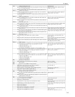
E710
IPC initialization error
0000 Error in initialization of IPC chip
Check the connection of cable, Replace the DC
controller PCB
0001 The status fails to be ready within 3 sec after the IPC chip starts up.
Check on connection of the cable
E711
IPC communication error
0001 Error is set to the error register of the IPC chip 4 times or more within 1.5 sec.
Check on connection of the cable, Replace the ADF
controller PCB, Replace the reader controller PCB
0002 Error is detected 4 times or more within 1.5 sec. after communication between the
finisher and the printer stops, and recovery ends in failure.
Check on connection of the cable, Replace the finisher
controller PCB, Replace the DC controller PCB
E712
Communication error between the ADF and the reader
0001 Communication between the reader and the ADF stops, and the communication cannot
recover for 5 sec. or more.
Check on connection of the cable, Replace the ADF
controller PCB, Replace the reader controller PCB
E713
Communication error between the finisher and the printer
0000 Communication between the finisher and the copier stops.
Check on connection of the cable, Replace the finisher
controller PCB, Replace the DC controller PCB
E716
Error in communication to cassette pedestal, 2 / 3 delivery unit
0000 Error in data communication with cassette pedestal
Check cable connection, replace pedestal PCB, replace
DC controller PCB
0001 Error in data communication with 2 / 3 delivery unit
Check cable connection, replace 2 / 3 delivery unit
PCB, replace DC controller PCB
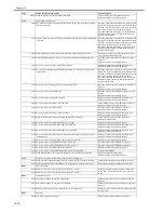
E717
Communication error with the NE controller
0001 The NE controller connected before the power is turned off fails to be recognized at
power-on.
Check on connection of the cable
To recover from the error: In service mode
COPIER>FUNCTION>CLEAR >ERR
0002 A break in the IPC, IPC communication fails to recover
E719
Communication error with the coin vender/card reader
0001 The coin vender connected before the power is turned off fails to be recognized at
power-on.
Check on connection of the cable
To recover from the error: In service mode
COPIER>FUNCTION>CLEAR >ERR
0002 - A break in the IPC cable connected to the coin vender, IPC communication fails to
recover
- A break in the paper pickup/delivery signal line
- Incorrect connection is detected (Short circuit in Tx and Rx of IPC)
0011 The card reader connected before the power is turned off fails to be recognized at
power-on.
0012 A break in the IPC cable connected to the card reader, IPC communication fails to
recover
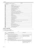
E730
PDL error
1001 PDL software error
Initialization error when a job starts.
Reset PDL, Turn OFF and back ON the main power
100A PDL software error
System error such as a failure in initialization occurs during job processing.
9004 Open interface communication error PAI communication error
with the external controller
Turn OFF and back ON the main power, Check on
connection of the Open interface board/cable, Replace
the external controller, Replace the Open interface
board, Replace the main controller PCB
9005 Connection error between the video cable and the external controller is detected.
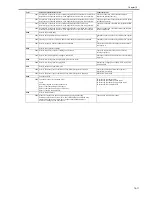
A006 PDL communication error PDL has no response
Reset PDL, Turn OFF and back ON the main power,
Check on connection of the UFR board, Re-install the
system, Replace the main controller PCB, Format and
re-install the whole system.
A007 PDL version mismatch Machine control software version
and PDL control software version do not match at start-up.
Reset PDL, Turn OFF and back ON the main power,
Format and re-install the whole system
B013 PDL built-in font error
Font data is corrupt at start-up.
Turn OFF and back ON the main power, Re-install the
system, Format and re-install the whole system.
C000 Initialization error
Format and re-install the whole system, Replace the
main controller PCB.
Code
Main Cause/Detail of Detection
Countermeasures
Summary of Contents for iR C3380 series
Page 1: ...Aug 29 2006 Service Manual iR C3380 2880 Series...
Page 2: ......
Page 6: ......
Page 23: ...Chapter 1 Introduction...
Page 24: ......
Page 26: ......
Page 52: ......
Page 53: ...Chapter 2 Installation...
Page 54: ......
Page 127: ...Chapter 3 Basic Operation...
Page 128: ......
Page 130: ......
Page 136: ......
Page 137: ...Chapter 4 Main Controller...
Page 138: ......
Page 160: ......
Page 161: ...Chapter 5 Original Exposure System...
Page 162: ......
Page 188: ...Chapter 5 5 24 F 5 68 4 Remove the original sensor 2 hook 1 F 5 69...
Page 189: ...Chapter 6 Laser Exposure...
Page 190: ......
Page 192: ......
Page 206: ......
Page 207: ...Chapter 7 Image Formation...
Page 208: ......
Page 256: ......
Page 257: ...Chapter 8 Pickup Feeding System...
Page 258: ......
Page 262: ......
Page 303: ...Chapter 9 Fixing System...
Page 304: ......
Page 306: ......
Page 321: ...Chapter 10 Externals and Controls...
Page 322: ......
Page 326: ......
Page 336: ...Chapter 10 10 10 F 10 10 2 Remove the check mark from SNMP Status Enabled...
Page 337: ...Chapter 10 10 11 F 10 11...
Page 359: ...Chapter 11 MEAP...
Page 360: ......
Page 362: ......
Page 401: ...Chapter 12 RDS...
Page 402: ......
Page 404: ......
Page 411: ...Chapter 13 Maintenance and Inspection...
Page 412: ......
Page 414: ......
Page 416: ...Chapter 13 13 2 F 13 1 8 9 1 2 3 3 5 6 7 10 11 12 13 14 4...
Page 421: ...Chapter 14 Standards and Adjustments...
Page 422: ......
Page 424: ......
Page 431: ...Chapter 15 Correcting Faulty Images...
Page 432: ......
Page 434: ......
Page 459: ...Chapter 16 Self Diagnosis...
Page 460: ......
Page 462: ......
Page 481: ...Chapter 17 Service Mode...
Page 482: ......
Page 484: ......
Page 571: ...Chapter 18 Upgrading...
Page 572: ......
Page 574: ......
Page 603: ...Chapter 19 Service Tools...
Page 604: ......
Page 606: ......
Page 609: ...Aug 29 2006...
Page 610: ......


