Chapter 2
2-13
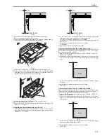
F-2-52
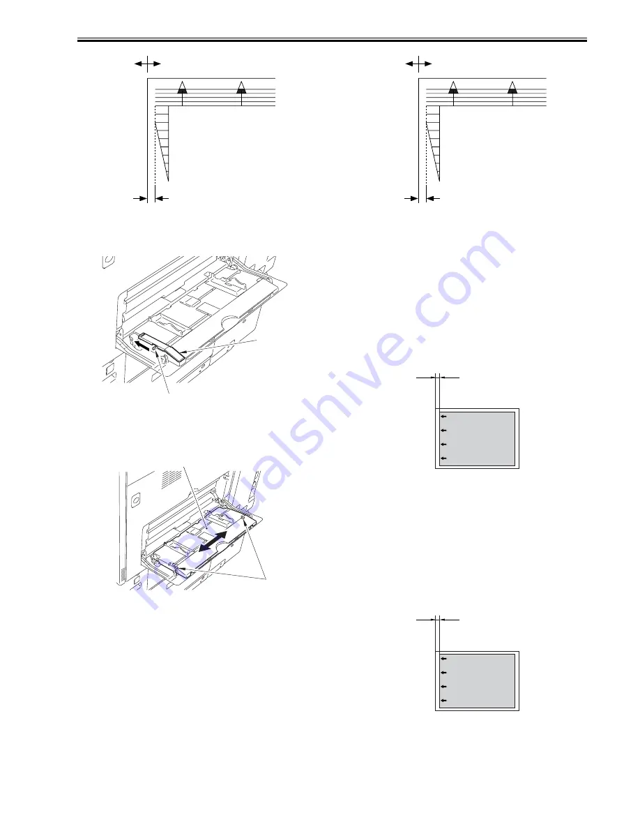
- If the value is not as indicated, make the following adjustments:
3) Remove the paper from the manual feed tray.
4) In case the MP side guide plate stopper [1] is attached, slide the knob [2]
in the direction of the arrow and unlock the stopper.
F-2-53
5) Loosen the 2 fixing screws [1] on the manual feed tray upper cover.
6) With reference to the value you took note of in step 2), move the manual
feed upper cover [2] back and forth. Moving it toward the rear of the
machine will increase the margin on the front side.
F-2-54
7) Tighten the fixing screw of the manual feed tray upper cover.
8) Place paper in the manual feed tray.
9) Make a copy; then, check to make sure that the margin on the image front
side is 2.5 +/-1.5 mm.
4. Adjusting the Margin (manual feed tray; 2nd side)
1) Make a double-sided copy using the manual feed tray as the source of
paper; then, check to make sure that the margin on the front side for the
2nd side is 2.5 +/-2.0 mm.
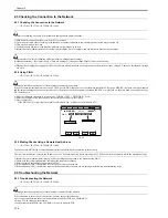
F-2-55
2) If the value is not as indicated, change the horizontal registration
adjustment value for the 2nd side for the manual feed tray.
- COPIER > ADJUST > FEED-ADJ > ADJ-MFRE
An increase by '1'(ADJ-MFRE) will decrease the margin on the front side
by 0.1 mm.
3) Record the new adjustment value on the service label.
- ADJ-MFRE
4) Press the Reset key twice to end service mode.
5. Adjusting the Margin Along the Leading Edge (1st side)
Make a copy using the cassette 1 as the source of paper; then, check to make
sure that the margin along the image leading edge (L1) is 4.0 +1.5/-1.0 mm.
If not, make adjustments as follows:
1) Make the following selections in service mode: COPIER > ADJUST >
FEED-ADJ > REGIST.
2) Change the setting to make adjustments. (A change of '1' will cause a shift
of 0.1 mm, with a higher value moving the image toward the leading
edge.)
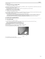
F-2-56
An increase in REGIST will shift the image toward the leading edge of
the paper.
3) Record the new adjustment value on the service label.
- REGIST
6. Adjusting the Margin Along the Leading Edge (2nd side)
Make a double-sided copy using the cassette 1 as the source of paper; then,
check to see if the margin along the image leading edge for the 2nd side (L)
is 4.0 +1.5/-1.0 mm. If not, make adjustments as follows:
1) Make the following selections in service mode: COPIER > ADJUST >
FEED-ADJ > RG-REFE.
2) Change the setting, and make adjustments. (A change of '1' will cause a
shift of 0.1 mm, with a higher setting moving the image toward the
leading edge.)
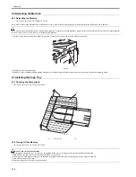
F-2-57
An increase in RG-REFE will shift the image toward the leading edge of
paper (toward the trailing edge of feed).
3) Record the new adjustment value on the service label.
- RG-REFE
0
2
4
6
8
10
(–)
(+)
2.5±1.5mm
[2]
[1]
[1]
[2]
0
2
4
6
8
10
(–)
(+)
2.5±2.0mm
image
L1
image
L1
Summary of Contents for iR C3380 series
Page 1: ...Aug 29 2006 Service Manual iR C3380 2880 Series...
Page 2: ......
Page 6: ......
Page 23: ...Chapter 1 Introduction...
Page 24: ......
Page 26: ......
Page 52: ......
Page 53: ...Chapter 2 Installation...
Page 54: ......
Page 127: ...Chapter 3 Basic Operation...
Page 128: ......
Page 130: ......
Page 136: ......
Page 137: ...Chapter 4 Main Controller...
Page 138: ......
Page 160: ......
Page 161: ...Chapter 5 Original Exposure System...
Page 162: ......
Page 188: ...Chapter 5 5 24 F 5 68 4 Remove the original sensor 2 hook 1 F 5 69...
Page 189: ...Chapter 6 Laser Exposure...
Page 190: ......
Page 192: ......
Page 206: ......
Page 207: ...Chapter 7 Image Formation...
Page 208: ......
Page 256: ......
Page 257: ...Chapter 8 Pickup Feeding System...
Page 258: ......
Page 262: ......
Page 303: ...Chapter 9 Fixing System...
Page 304: ......
Page 306: ......
Page 321: ...Chapter 10 Externals and Controls...
Page 322: ......
Page 326: ......
Page 336: ...Chapter 10 10 10 F 10 10 2 Remove the check mark from SNMP Status Enabled...
Page 337: ...Chapter 10 10 11 F 10 11...
Page 359: ...Chapter 11 MEAP...
Page 360: ......
Page 362: ......
Page 401: ...Chapter 12 RDS...
Page 402: ......
Page 404: ......
Page 411: ...Chapter 13 Maintenance and Inspection...
Page 412: ......
Page 414: ......
Page 416: ...Chapter 13 13 2 F 13 1 8 9 1 2 3 3 5 6 7 10 11 12 13 14 4...
Page 421: ...Chapter 14 Standards and Adjustments...
Page 422: ......
Page 424: ......
Page 431: ...Chapter 15 Correcting Faulty Images...
Page 432: ......
Page 434: ......
Page 459: ...Chapter 16 Self Diagnosis...
Page 460: ......
Page 462: ......
Page 481: ...Chapter 17 Service Mode...
Page 482: ......
Page 484: ......
Page 571: ...Chapter 18 Upgrading...
Page 572: ......
Page 574: ......
Page 603: ...Chapter 19 Service Tools...
Page 604: ......
Page 606: ......
Page 609: ...Aug 29 2006...
Page 610: ......


