background image

Chapter 1

9

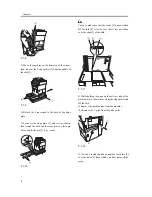
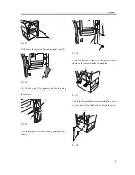
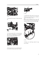
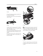
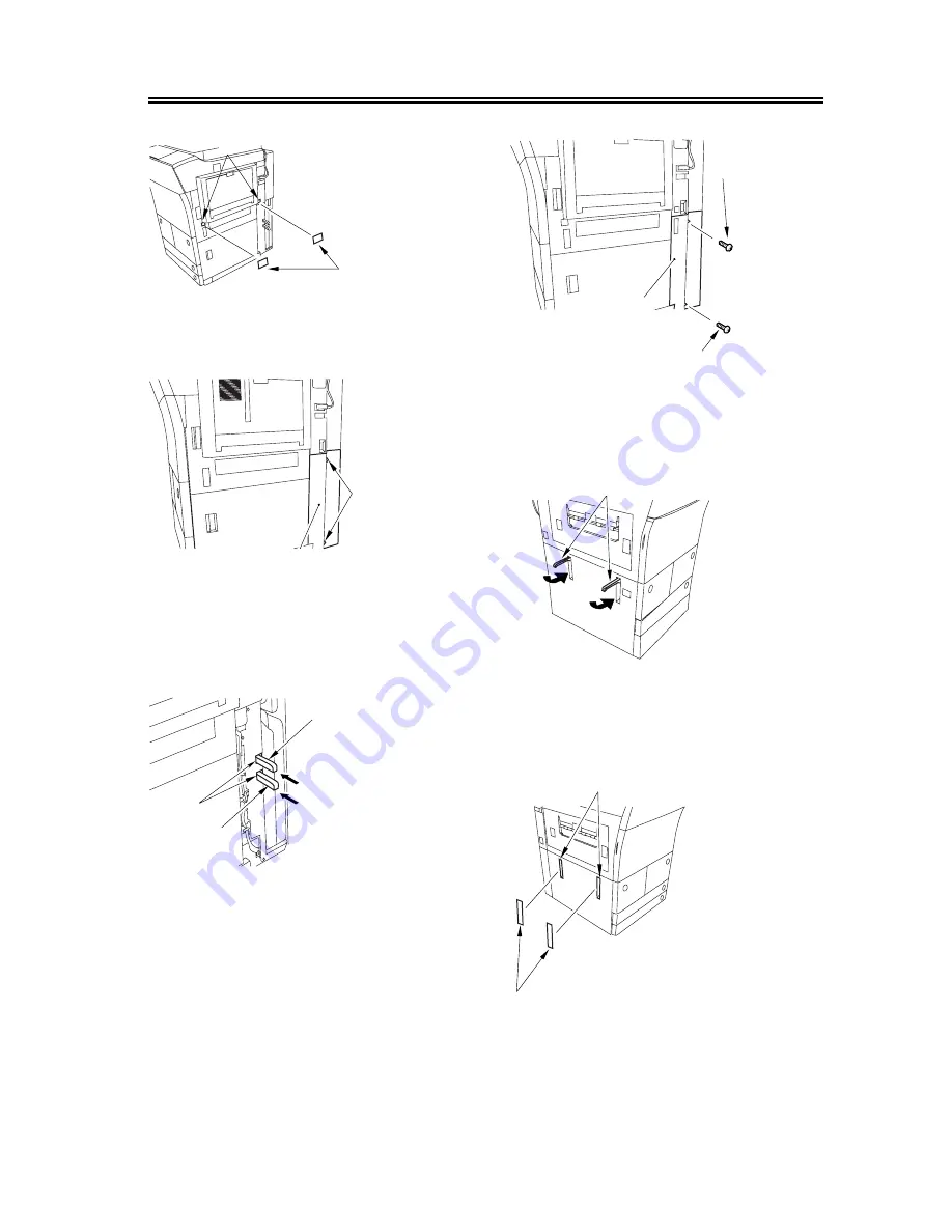
F-1-13

12) Remove the 2 screws [1], and rear right cover [2].

F-1-14

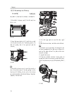
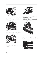
13) Fit the 2 grips [1] you removed in the foregoing
step in the compartment [2] found at the rear right of
the machine.

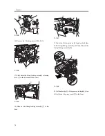
F-1-15

14) Fix the right cover (lower rear) [2] in place with 2
screws [1].

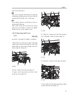
F-1-16

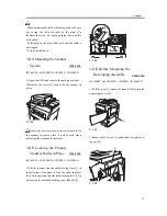
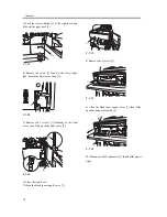
15) Shift down the 2 grips [1] on the delivery side as
shown so that they are inside the machine.

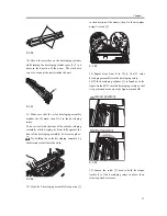
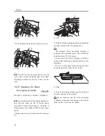
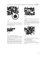
F-1-17

16) Fit the 2 included delivery assembly face plates
over the holes [1] in which you have fitted the grips.

F-1-18

[2]

[1]

[1]

[2]

[2]

[1]

[1]

[1]

[2]

[1]

[1]

[1]

[2]

Summary of Contents for iR C6800 Series

Page 1: ...Jan 20 2005 Installation Procedure iR C6800 Series...

Page 2: ......

Page 3: ...need arises In the event of major changes in the contents of this manual over a long or short period Canon will issue a new edition of this manual The following paragraph does not apply to any countri...

Page 4: ...uiring care to avoid combustion fire Indicates an item prohibiting disassembly to avoid electric shocks or problems Indicates an item requiring disconnection of the power plug from the electric outlet...

Page 5: ...ed to indicate Low The voltage value however differs from circuit to circuit In addition the asterisk as in DRMD indicates that the DRMD signal goes on when 0 In practically all cases the internal mec...

Page 6: ......

Page 7: ...Switch 27 1 2 14Setting Up the Paper Cassette 27 1 2 15Changing the Deck Paper Size right left 28 1 2 16Fitting the Color Toner Cartridge 29 1 2 17Supplying Black Toner 30 1 2 18Cleaning the Intermedi...

Page 8: ...Installing the NE Controller A1 44 1 6 1NE Controller A1 Installation Procedure 44 1 7 Installing the Original Tray 50 1 7 1Checking the Contents 50 1 7 2Installation 50 1 8 Installing the Key Switch...

Page 9: ...Chapter 1 Installation Procedure...

Page 10: ...ar a source of fire or in an area subject to dust or ammonium gas If the area is exposed to the direct rays of the sun the windows must be furnished with curtains The site must be well ventilated Howe...

Page 11: ...te having a pin hole 1 Be sure that the space will be on this side left side The side of the slope plate having a pin hole left is where the delivery side of the machine will be with the front of the...

Page 12: ...he environment of the site meets the following requirements F 1 4 1 Humidity 2 Temperature 1 1 3 Checking the Contents 0002 6404 iR C6800C iR C6800CN iR 5800C iR 5800CN The following shows the content...

Page 13: ...lack developing assembly black 1 pc 4 Color developing assembly cyan magenta yellow 1 pc each 5 Black developing assembly locking plate 1 pc 6 Process unit cover 1 pc 7 Touch pen 1 pc 8 Service book c...

Page 14: ...up assembly face place 2 pc 18 Delivery assembly face plate 2 pc 19 Binding screw M4x8 2 pc 20 RS tightening screw M4x8 3 pc 21 Left deck locking plate 1 pc 22 No Copy label non 100 V model 3 pc 23 Gl...

Page 15: ...ork in a group of 4 persons when lifting it 3 Be sure to turn the 2 adjusters front found on the bottom of the machine clockwise to release them These adjusters can slip off the machine when the machi...

Page 16: ...fit the pin 2 1 pc each F 1 10 Check to make sure that the caster 1 has not rolled off the skid 2 Also be sure that it has not ridden over the edge 3 of the skid F 1 11 8 While holding the grips on t...

Page 17: ...ound at the rear right of the machine F 1 15 14 Fix the right cover lower rear 2 in place with 2 screws 1 F 1 16 15 Shift down the 2 grips 1 on the delivery side as shown so that they are inside the m...

Page 18: ...the direction of B Pulling the lever 1 of the release spacer horizontally by mistake can damage the pickup assembly Take full care F 1 21 3 Close the upper right cover and the lower right cover 4 Pus...

Page 19: ...ay the screw used to fix the scanner system in plate It will be used when relocating the machine in the future 1 2 5 Locking the Primary Transfer Roller in Place 0002 6568 iR C6800C iR C6800CN iR 5800...

Page 20: ...strap 2 F 1 28 5 Remove the 2 screws 1 binding of the front cover then fully open the front cover 2 F 1 29 6 Close the right deck 7 Open the black toner supply cover 1 F 1 30 8 Remove the 3 screws 1...

Page 21: ...ess unit cover 1 from the box then detach the drum stop tool 2 fitted to its back F 1 36 14 Hold the drum fixing member 1 in place using the drum stop tool 2 Then using a screwdriver remove the drum f...

Page 22: ...n of the arrow F 1 40 18 Slide out the fixing feeding assembly 1 to the front F 1 41 19 Push the 2 slide out hook 1 found on both sides of the fixing feeding assembly and fully slide out the fixing fe...

Page 23: ...r developing assembly yellow magenta cyan from its package box 2 Push the lever 1 of the developing rotary solenoid once by hand then turn the developing rotary 2 counterclockwise by hand If you turn...

Page 24: ...Place A3 paper on a smooth table and place the appropriate color developing assembly 8 With the developing cylinder of the color developing assembly facing upward detach he tape 1 then pull out the p...

Page 25: ...y fit its rear in place Try holding the color developing assembly by both its ends to facilitate the work F 1 52 12 Close the 2 developing assembly fixing arms 1 in the direction of the arrows then fi...

Page 26: ...ts 1 Remove the 2 screws 1 and detach the joint plate 2 F 1 57 2 Hold the black developing assembly in lengthwise direction and take it out of its package box The machine s black developing assembly i...

Page 27: ...2 at the rear of the developing assembly matches the left guide 3 of the machine Be sure also that the rib 4 at the front of the developing assembly matches the right guide at the front of the machin...

Page 28: ...joint plate 1 in place using 2 binding screws 2 F 1 66 11 Remove the paper put between the photosensitive drum and the developing rotary 12 Fit the protrusion 1 of the included black assembly locking...

Page 29: ...it 0002 6689 iR C6800C iR C6800CN iR 5800C iR 5800CN 1 Match the area 1 where the resistance of the high voltage cable is found in the upper left of the front against the 4 pins 2 of the host machine...

Page 30: ...ing the drum stop tool Thereafter tighten the drum fixing screw 4 using a screwdriver Be sure to fix the protrusion 5 of the drum stop tool in place with a screw while matching it against the notch 6...

Page 31: ...primary charging wire and the shielding plate for soiling If it is soiled with dirt or paper lint clean it using alcohol F 1 79 13 Disconnect the connector 1 and remove the screw 2 14 Take out the pr...

Page 32: ...place using a screw 3 F 1 83 23 Close the right deck 24 Slide out the fixing feeding assembly 25 Open the color toner supply cover 1 F 1 84 26 Fix the process unit cover 1 in place using the 2 RS tig...

Page 33: ...ver 1 F 1 88 4 Peel off the tape 2 used to keep the tag 1 in place F 1 89 5 Remove the 2 fixing nip releasing screws 1 F 1 90 6 Check the fixing web for any slack as necessary perform steps 7 and 8 7...

Page 34: ...detach from the bottle F 1 94 4 Hold the black toner bottle with its mouth 1 on the right side then fit it in the supply case 2 of the machine F 1 95 5 Shift the lock lever 1 upward to lock the black...

Page 35: ...the grounding wire to ground the machine 2 Connect the machine s power plug to the power outlet and turn on the main power 1 3 Execute the following in service mode to disable initial rotation COPIER...

Page 36: ...k into the machine 8 As necessary perform the same work for the other cassette 9 Open the front cover then detach the color toner cartridge supply tab 1 from its back F 1 102 10 Peel the 2 color toner...

Page 37: ...rvice mode to register the front deck paper size for the right deck COPIER OPTION CST P SZ C1 for the left deck COPIER OPTION CST P SZ C2 A4 0 B5 1 LTR 2 8 Press the Reset key twice to end service mod...

Page 38: ...Check to see that the warm up period is over i e Keep paper in the machine so that the control panel will indicate the message Ready to Copy 2 Execute the following service mode item to supply black...

Page 39: ...s appeared asking you to remove the printout remove it from the copyboard glass 6 Press test print 2 In a while the machine prints out Test Print 2 7 Place the printout of Test Print 2 on the copyboar...

Page 40: ...k to see that the horizontal registration left right margin L1 of the copy on paper from cassette 3 is 2 5 1 5 mm F 1 112 1 Paper feed direction 5 Tighten the screw 6 Close the upper right cover and t...

Page 41: ...on and slide out the right deck 2 Open the upper right cover and the lower right cover 3 Loosen the 2 screws 1 and insert a screwdriver 2 through the hole in the front right stay then turn the adjusti...

Page 42: ...o be sure that the leading edge registration leading edge margin L1 of the copy made on paper from the cassettes and the deck is 4 0 1 5 1 0 mm If not go through the following Make the following selec...

Page 43: ...2 F 1 125 4 Fit the touch pen 1 in place on the control panel F 1 126 5 Clean up the area around the machine and fill out the service book 6 Make necessary settings in user mode date time and service...

Page 44: ...o If the machine is not connected to a network its control panel will display the message Check Connection to the Network To disable the message set the following service mode item to 0 COPIER OPTION...

Page 45: ...ed error message To disable the indication of such a message use the following service mode item set it to 0 COPIER OPTION BODY NWERR SCREW 1 3 2 Using the PING Utility 0002 6739 iR C6800C iR C6800CN...

Page 46: ...dministrator that you will be checking the network connection using the PING utility 2 Ask the system administrator for the remote home address you can use 3 Enter the remote home address to the appro...

Page 47: ...02 6751 iR C6800C iR C6800CN iR 5800C iR 5800CN A loopback address comes back before it reaches the network PCB as such you can find out whether the machine s TCP IP settings are correct by executing...

Page 48: ...faulty check the connectors used to connect the network PCB c The network PCB is faulty replace the network PCB If OK is indicated suspect a fault in the user s network environment contact the system...

Page 49: ...C1 1 Card reader base 1 pc 2 RS tightening screw M4x10 2 pc F 1 129 1 5 3 Installation 0002 6753 iR C6800C iR C6800CN iR 5800C iR 5800CN 1 Make the following selections in the host machine s service...

Page 50: ...t the right cover upper you removed in step 3 10 Turn on the main power switch and check that a message has appeared asking for a control card 11 Insert a control card and check to see that the machin...

Page 51: ...ess gateway address subnet mask Take care If you fail to register system control group and system control ID No you will not be able to perform register card to device as part of NSA setup work 3 Unde...

Page 52: ...s must be identified by type length diameter and location 5 The setup data for the controller must be saved to a PC at the service station 1 Remove the 2 screws 2 of the top cover 1 of the controller...

Page 53: ...he DIP switch SW2 7 2 to the ON side otherwise shift the bit to the OFF side F 1 143 If IC6 1 is not found you need not mount one If you are mounting or replacing a ROM IC6 1 to upgrade the controller...

Page 54: ...m signal transmission level to 16 dBm ON OFF set the modem signal transmission level to 14 dBm SW3 1 see right OFF ON set the modem signal transmission level to 12 dBm SW3 2 ON ON set the modem signal...

Page 55: ...the push switch SW4 3 will cause LED5 1 red to go off indicating that the RAM has been initialized T 1 3 SW2 4 ON SW2 5 OFF SW2 6 OFF SW2 7 See step 8 SW2 8 OFF SW2 bits Setting LED1 LED2 LED3 2 1 LED...

Page 56: ...d If the work has failed go through steps 10 through 12 to initialize the RAM and start the setup work once again Be sure to contact the service station to find out if the settings are correct 17 Call...

Page 57: ...made F 1 153 20 Attach the switch settings label 1 to the top cover of the controller and record the new switch settings 21 Fix the top cover 2 of the controller in place using 2 screws 3 When doing...

Page 58: ...00CN iR 5800C iR 5800CN 1 Original holder 1 pc 2 Stepped screw M4 2 pc F 1 155 1 7 2 Installation 0002 6754 iR C6800C iR C6800CN iR 5800C iR 5800CN 1 Fit the 2 stepped screws 2 in the right cover uppe...

Page 59: ...N 1 Turn off the control panel power switch 2 Turn off the main power switch 3 Disconnect the power plug 4 Disconnect the reader communications cable 1 5 Remove the 2 screws 2 and detach the right cov...

Page 60: ...2 Mount the right cover upper rear you removed in step 5 13 Connect the power plug and turn on the main power switch 14 Start service mode and make the following selections COPIER FUNCTION INSTALL KEY...

Page 61: ...Chapter 2 Relocating the Machine...

Page 62: ...in place as soon as developing assemblies have been removed Also be sure to fix the developing assembly fixing arm in place using a screw F 2 1 6 Tape the fixing feeding assembly releasing lever in pl...

Page 63: ...Jan 20 2005...

Page 64: ......

Reviews: