Chapter 1
20
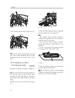
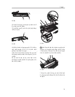
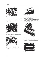
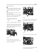
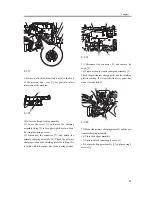
F-1-63
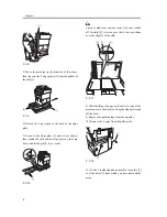
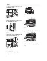
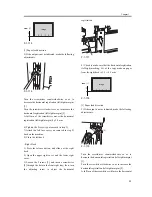
8) Route the high-voltage cable [1] of the black
developing assembly along the side of the toner
supply mouth [2].
F-1-64
9) Connect the connector [1] found at the inside front.
F-1-65
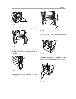
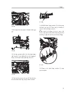
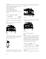
10) Fix the joint plate [1] in place using 2 binding
screws [2].
F-1-66
11) Remove the paper put between the photosensitive
drum and the developing rotary.
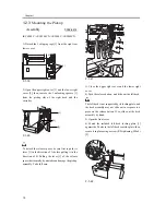
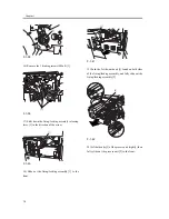
12) Fit the protrusion [1] of the included black
assembly locking plate into the positioning hole [2]
found at the rear of the machine.
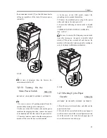
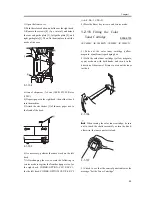
F-1-67
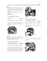
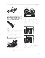
13) Fix the black developing assembly locking plate
[1] in place using the included screw (binding; M4x8)
[2].
F-1-68
[1]
[2]
[1]
[2]
[1]
[1]
[2]
[2]
[1]
[1]
[2]
Summary of Contents for iR C6800 Series
Page 1: ...Jan 20 2005 Installation Procedure iR C6800 Series...
Page 2: ......
Page 6: ......
Page 9: ...Chapter 1 Installation Procedure...
Page 61: ...Chapter 2 Relocating the Machine...
Page 63: ...Jan 20 2005...
Page 64: ......


