Chapter 1
46
T-1-1
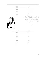
10) Connect the power plug to the power supply unit;
then, check to see that LED1 [1] (green) on the PCB
goes on.
F-1-145
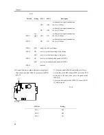
11) Initialize the RAM of the controller as follows:
Set the bits of the DIP switch (SW2) [1] on the PCB
as shown in the table; then, press the push switch
(SW4) [2].
A press on the push switch (SW4) [2] causes LED 3
[3] (red) to go on.
T-1-2
Notation
Setting
SW3-1 SW3-2
Description
OFF OFF
set the modem signal transmission
level to -16 dBm.
ON OFF
set the modem signal transmission
level to -14 dBm.
SW3-1
see
right
OFF ON
set the modem signal transmission
level to -12 dBm.
SW3-2
ON ON
set the modem signal transmission
level to -10 dBm.
SW3-3
OFF
keep it to OFF at all tiems.
SW3-4
ON
use it to set the line setting to touch tone.
OFF
use it to set the line setting to dial pulse.
SW3-5
ON
use it to set the dial pulse speed to 20 PPS.
OFF
use it to set the dial pulse speed to 10 PPS.
SW3-6
-
not used
LED1 LED2 LED3
2
1
LED5
LED6
LED4
IC6
SW1
SW4
SW3
6
1
BAT1
CN4
1
2
CN3
CN2
SW2
[1]
SW2 bits
Setting
SW2-1 OFF
SW2-2 OFF
SW2-3 ON
Summary of Contents for iR C6800 Series
Page 1: ...Jan 20 2005 Installation Procedure iR C6800 Series...
Page 2: ......
Page 6: ......
Page 9: ...Chapter 1 Installation Procedure...
Page 61: ...Chapter 2 Relocating the Machine...
Page 63: ...Jan 20 2005...
Page 64: ......


