Chapter 1
49
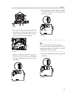
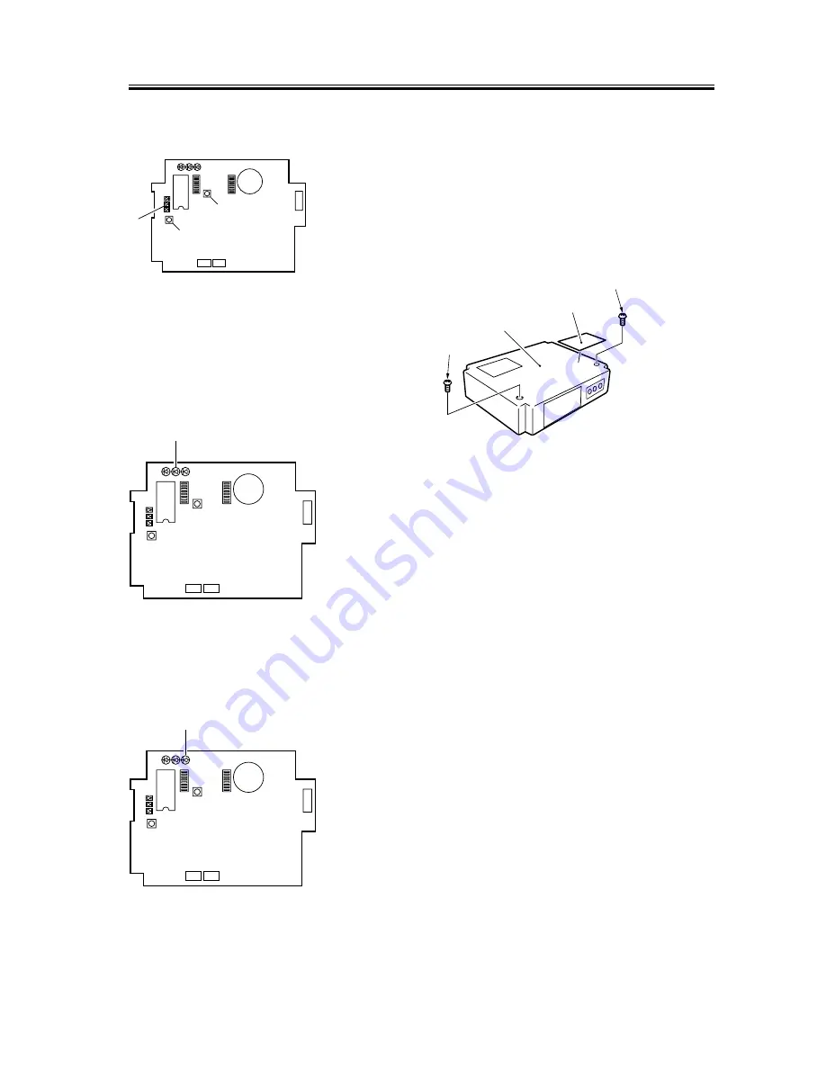
A press on the push switch (SW1) [3] while LED6 [2]
is flashing will cancel the transmission.
F-1-151
18) Check to see that the communication between the
controller and its host machine is normal.
Connect the host machine's power plug, and turn on
the power switch; then, check to see that LED2
(orange) [2] flashes.
F-1-152
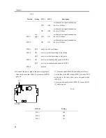
19) Press the Start key on the host machine; then,
check that LED3 (pink) flashes each time delivery
is made.
F-1-153
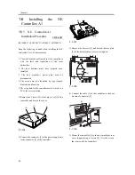
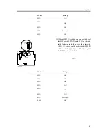
20) Attach the switch settings label [1] to the top cover
of the controller, and record the new switch
settings.
21) Fix the top cover [2] of the controller in place
using 2 screws [3]. When doing so, check to be sure
that the cable of the power supply unit is fixed in
place to the cable guide inside the controller and is
not trapped by the top cover [2].
F-1-154
LED1 LED2 LED3
2
1
LED5
LED6
IC6
SW1
SW4
SW3
6
1
BAT1
CN4
1
2
CN3
CN2
SW2
[2]
[1]
[3]
LED4
LED1 LED2 LED3
2
1
LED5
LED6
LED4
IC6
SW1
SW4
SW3
6
1
BAT1
CN4
1
2
CN3
CN2
SW2
[2]
LED1 LED2 LED3
2
1
LED5
LED6
LED4
IC6
SW1
SW4
SW3
6
1
BAT1
CN4
1
2
CN3
CN2
SW2
[1]
[3]
[2]
[3]
[1]
Summary of Contents for iR C6800 Series
Page 1: ...Jan 20 2005 Installation Procedure iR C6800 Series...
Page 2: ......
Page 6: ......
Page 9: ...Chapter 1 Installation Procedure...
Page 61: ...Chapter 2 Relocating the Machine...
Page 63: ...Jan 20 2005...
Page 64: ......


