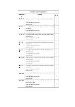
DV-UNT-
K
for the developing unit, indicates the number of sheets that have
passed.
(count retained by DC controller PCB)
- if you have replaced the developing unit (Bk), reset the counter
reading.
- if you have replaced the DC controller PCB, enter the reading
indicated before the replacement.
Do not reset or change the reading of the counter unless the foregoing
is true; otherwise, the image density will likely be wrong, causing
fogging or damage to the drum by carrier. If you inadvertently reset or
changed the reading, replace the developing unit (Bk), and reset the
reading once again.
The machine's ATR control uses the patch image density measured at
specific timing and target value to correct toner supply amounts. The
target density on the other hand is also corrected for individual colors
and is corrected for Bk based on the cumulative number of images that
have been formed (monitored by the counter in question).
1
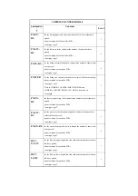
DV-CAR-
Y/M/C
toner life Y/M/C (count retained by DC controller PCB)
YMC Toner Life
Reset the setting to '0' when you have replaced the developing
assembly; any value may be entered.
- if you have replaced the DC control PCB, enter the reading indicated
before the replacement.
Estimated life 500,000 prints
1
COPIER>COUNTER>MISC
Subheadin
g
Contents
Level
Summary of Contents for iR C6800 Series
Page 1: ...Jan 20 2005 Portable Manual iR C6800 Series ...
Page 2: ......
Page 6: ......
Page 12: ......
Page 13: ...Chapter 1 Maintenance and Inspection ...
Page 14: ......
Page 16: ......
Page 20: ...Chapter 1 1 4 Under high humidity and high temperature condition 85 000 images ...
Page 51: ...Chapter 2 Standards and Adjustments ...
Page 52: ......
Page 79: ...F 2 27 1 ...
Page 99: ...F 2 88 F 2 89 1 OK NG NG ...
Page 110: ......
Page 111: ...Chapter 3 Error Code ...
Page 112: ......
Page 114: ......
Page 172: ......
Page 173: ...Chapter 4 User Mode Items ...
Page 174: ......
Page 176: ......
Page 188: ...LIPS emulation 12 items utility printer initialize yes no Item Description ...
Page 190: ......
Page 191: ...Chapter 5 Service Mode ...
Page 192: ......
Page 380: ......
Page 381: ...Chapter 6 Outline of Components ...
Page 382: ......
Page 384: ......
Page 387: ...F 6 1 SL7 CL3 CL2 SL6 SL8 SL9 SL2 SL1 SL4 SL3 SL5 CL1 SL10 SL11 SL12 ...
Page 397: ...F 6 5 FM2 FM10 FM11 FM12 FM6 FM3 FM4 FM8 FM9 FM5 FM7 FM1 ...
Page 407: ...F 6 9 PS65 PS38 PS39 PS46 PS44 PS45 PS52 PS53 PS58 PS59 PS37 ...
Page 417: ...F 6 13 13 2 5 3 14 15 16 9 6 12 7 1 11 4 25 24 21 23 19 20 31 29 28 27 26 22 18 17 32 30 10 8 ...
Page 418: ......
Page 419: ...Chapter 7 System Construction ...
Page 420: ......
Page 422: ......
Page 443: ...Chapter 8 Upgrading ...
Page 444: ......
Page 446: ......
Page 455: ...Jan 20 2005 ...
Page 456: ......


