Chapter 13
13-2
13.2 Scanning System
13.2.1 Procedure after Replacing the CIS
0013-1269
iR1020J / iR1024J / iR1020 / iR1024 / iR1024A / iR1024N / iR1024F /
iR1024i / iR1024iF
After replacing the contact image sensor (CIS), go through the following
steps to perform inter-channel output correction:
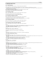
1) Enter the service mode.
Sequentially press the Additional functions key, 2 key, 8 key, and Additional
functions key on the operation panel.
2) Press the arrow key on the touch panel to display "TEST MODE".
3) Press [OK].
4) Press the [2] key to display "SCAN TEST".
5) Press the [1] key to display "SHADING".
6) Press [OK].
After completion of the above procedure, the contact sensor output is com-
pensated and parameters are set automatically.
After completion of automatic adjustment, "OK" is displayed.
13.2.2 Procedure after Replacing the Copyboard Glass (if
equipped with SEND functions)
0013-9587
iR1020J / iR1024J / iR1020 / iR1024 / iR1024A / iR1024N / iR1024F /
iR1024i / iR1024iF
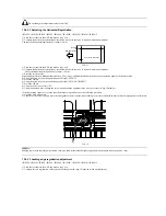
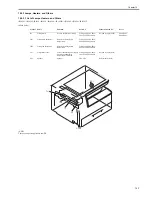
After replacing the copyboard glass, enter the correction values (X, Y, Z) of
the standard white plate which are indicated on the back of the new copy-
board glass in the service mode.
Correction value (X): Service mode>#SCAN>#SCAN NUMERIC>No.213
Correction value (Y): Service mode>#SCAN>#SCAN NUMERIC>No.214
Correction value (Z): Service mode>#SCAN>#SCAN NUMERIC>No.215
Also, rewrite the values on the service label.
F-13-6
13.3 Electrical Components
13.3.1 Procedure after Replacing the Image Processor
PCB
0013-1270
iR1020J / iR1024J / iR1020 / iR1024 / iR1024A / iR1024N / iR1024F /
iR1024i / iR1024iF
If you have replaced the image processor PCB with a new one, perform the
following operations:
- Using the service support tool, download the latest firmware (System/Boot/
PCL*1) and language files.
*1: if equiped with PCL functions.
- Input the all value printed on the service label affixed to the rear cover.
Make the following adjustments:
- Correction of output between CIS channels
1) Enter the service mode.
Sequentially press the Additional functions key, 2 key, 8 key, and Additional
functions key on the operation panel.
2) Press the arrow key on the touch panel to display "TEST MODE".
3) Press [OK].
4) Press the [2] key to display "SCAN TEST".
5) Press the [1] key to display "SHADING".
6) Press [OK].
After completion of the above procedure, the contact sensor output is com-
pensated and parameters are set automatically.
After completion of automatic adjustment, "OK" is displayed.
- Read position adjustment (Stream reading: Only when the ADF is installed)
1) Enter the service mode.
Sequentially press the Additional functions key, 2 key, 8 key, and Additional
functions key on the operation panel.
2) Press the arrow key on the touch panel to display "TEST MODE".
3) Press [OK].
4) Press the [2] key to display "SCAN TEST".
5) Press the [3] key to display "SHEET POS ADJ".
The optical system starts scanning. Several seconds later, automatic adjust-
ment of the reading position finishes and "OK" appears.
If automatic adjustment fails, "NG" appears. Perform the following pro-
cedure:
Clean the platen guide of the DADF and the document glass of the host ma-
chine, and then retry auto adjustment.
13.3.2 Actions to Take before All Clearing (Backing up the
User Data)
0013-1271
iR1020J / iR1024J / iR1020 / iR1024 / iR1024A / iR1024N / iR1024F /
iR1024i / iR1024iF
- Performing the all-clear operation in the service mode (#CLEAR > ALL)
erases/initializes the user data such as address data and user mode set-
tings.
Be sure to back up the user data with the data export function before
starting the all-clear operation, and then load the user data with tbe data
import function.
- To export and import user data, a PC and a USB cable are required. Have
them on hand.
a. Exporting user data
1) Output a user data list in the following user mode.
Additional functions key > Report Setting > Plint List > User Data List
2) Press the following keys to enter the service mode.
Additional functions key > 2 key > 8 key > Additional functions key
3) Select "#SYSTEM" using the arrow key, and then press the OK.
4) Select "#SYSTEM SW" using the arrow key, and then press the OK.
5) Press the following keys to display "SW003."
# > 0 key > 3 key
Message: #SYSTEM SW003 00001000
6) Position the cursor at Bit-6 (second from left) using the arrow key, and
then press the 1 key.
Message: #SYSTEM SW003 01001000
7) Press the OK key. Check that "SW003" changes to "SW004".
Message: #SYSTEM SW004 00000000
8) Press the Reset key to exit the service mode.
9) Turn off the main power switch, and then turn it on again.
10) Start the PC and connect it to this machine with a USB cable.
11) Open My Computer on the PC to check that the "Removable Disk" icon
is displayed. If the "Removable Disk" icon is not displayed, repeat the
above procedure starting with step 1.
In case for using Windows Vista, the progress bar on the display may occa-
sionally be stuck for a few minutes, while the user data (user_data.dat) im-
porting is successfully being transacted. Should the progress bar be still stuck
for few minutes more, retry to set up the connection.
12) Double-click the "Removable Disk" icon, and then copy the user data
(address_book.abk and user_data.dat) onto the Desktop.
13) Close the window on the Desktop.
14) Turn off the main power switch of this machine.
15) Disconnect the USB cable from this machine.
b. Importing user data
1) Press the following keys to enter the service mode.
Additional functions key > 2 key > 8 key > Additional functions key
2) Select "#SYSTEM" using the arrow key, and then press the OK.
4) Select "#SYSTEM SW" using the arrow key, and then press the OK.
5) Press the following keys to display "SW003".
# > 0 key > 3 key
Message: #SYSTEM SW003 00001000
5) Check that Bit-6 (second from left) is set to "1". If Bit-6 is not set to "1",
position the cursor at this bit using the arrow key and then press the 1 key.
Message: #SYSTEM SW003 01001000
6) Press the OK key. Check that "SW003" changes to "SW004".
Message: #SYSTEM SW004 00000000
7) Press the Reset key to exit the service mode.
8) Turn off the main power switch, and then turn it on again.
9) Open My Computer on the PC to check that the "Removal Disk" icon is
displayed.
11) Write the user data (address_book.abk and user_data.dat) copied onto
the Desktop as described in "a. Exporting user data" over the removable
disk.
12) Disconnect the USB cable from the machine.
13) Turn off the main power switch of the machine.
14) Perform steps 1) to 4) again to reset Bit-6 of "SW003" to "0".
15) Press the OK key. When "SW003" changes to "SW004", press the Reset
key to exit the service mode.
8 2 0 6 8 6 6 7 9 3 4 9
c o r r e c t o n
va l u e ( X )
c o r r e c t o n
va l u e ( Y )
c o r r e c t o n
va l u e ( Z )
Summary of Contents for iR1020 Series
Page 1: ...Sep 1 2008 Service Manual iR1020 1021 1024 1025 Series ...
Page 2: ......
Page 6: ......
Page 17: ...Chapter 1 Introduction ...
Page 18: ......
Page 20: ......
Page 49: ...Chapter 1 1 29 ...
Page 50: ......
Page 51: ...Chapter 2 Installation ...
Page 52: ......
Page 54: ......
Page 61: ...Chapter 2 2 7 ...
Page 62: ......
Page 63: ...Chapter 3 Basic Operation ...
Page 64: ......
Page 66: ......
Page 73: ...Chapter 3 3 7 ...
Page 74: ......
Page 75: ...Chapter 4 Original Exposure System ...
Page 76: ......
Page 78: ......
Page 87: ...Chapter 5 Laser Exposure ...
Page 88: ......
Page 90: ......
Page 94: ......
Page 95: ...Chapter 6 Image Formation ...
Page 96: ......
Page 98: ......
Page 103: ...Chapter 7 Pickup Feeding System ...
Page 104: ......
Page 106: ......
Page 120: ......
Page 121: ...Chapter 8 Fixing System ...
Page 122: ......
Page 124: ......
Page 135: ...Chapter 9 External and Controls ...
Page 136: ......
Page 138: ......
Page 151: ...Chapter 10 Original Feeding System ...
Page 152: ......
Page 154: ......
Page 156: ...Chapter 10 10 2 M2001 ADF motor Symbol Name ...
Page 170: ......
Page 171: ...Chapter 11 e maintenance imageWARE Remote ...
Page 172: ......
Page 174: ......
Page 184: ......
Page 185: ...Chapter 12 Maintenance and Inspection ...
Page 186: ......
Page 188: ......
Page 190: ......
Page 191: ...Chapter 13 Standards and Adjustments ...
Page 192: ......
Page 194: ......
Page 201: ...Chapter 14 Correcting Faulty Images ...
Page 202: ......
Page 204: ......
Page 214: ......
Page 215: ...Chapter 15 Self Diagnosis ...
Page 216: ......
Page 218: ......
Page 224: ......
Page 225: ...Chapter 16 Service Mode ...
Page 226: ......
Page 230: ......
Page 232: ...Chapter 16 16 2 Makes various status checks such as contact sensor sensor and print status ...
Page 278: ......
Page 279: ...Chapter 17 Upgrading ...
Page 280: ......
Page 282: ......
Page 297: ...Chapter 18 Service Tools ...
Page 298: ......
Page 299: ...Contents Contents 18 1 Service Tools 18 1 18 1 1 Special Tools 18 1 ...
Page 300: ......
Page 302: ......
Page 303: ...Sep 1 2008 ...
Page 304: ......


