Chapter 15
15-2
15.2 Jam Code
15.2.1 Jam Codes (Main body)
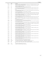
0013-1433
iR1020J / iR1024J / iR1020 / iR1024 / iR1024A / iR1024N / iR1024F / iR1024i / iR1024iF
T-15-2
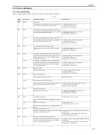
E719
0000
Erroneous communication with card reader (serial communication)
- Disconnection from the card reader has been detected since
communication started after confirmation of normal
connection to the card reader (after power-on).
- A serial communication error has occurred. (The serial
communication error cannot be recovered.)
- Check the connectors of the card reader and image processor
PCB.
- Replace the card reader for normal connection.
- Replace the image processor PCB.
0001
Erroneous communication with coin vendor (serial communication)
- Disconnection from the coin vendor has been detected since
communication started after confirmation of normal
connection to the coin vendor (after power-on).
- A serial communication error has occurred. (The serial
communication error cannot be recovered.)
- Check the connection between the image processor PCB and
serial PCB.
- Check the connectors of the serial PCB and coin vendor for
normal connection.
- Replace the serial PCB.
- Check the coin vendor.
- Replace the image processor PCB.
E730
0000
inside error of the image processor PCB (PDL system error)
- Replace the image processor PCB.
The inside of the image processor PCB is faulty.
E733
0000
Erroneous communication between controller and printer
Cannot communicate with the printer at startup.
- Check the connectors of the DC controller PCB and image
processor PCB for normal connection.
- Check the power supply of the printer (Check whether
initialization is performed at startup).
- Replace the DC controller PCB or image processor PCB.
E736
0000
CCU communication error
The installed modem PCB is incompatible.
- Check the connectors of the image processor PCB and modem.
- Replace the modem PCB.
- Replace the image processor PCB.
E739
0000
Erroneous communication between controller and network board
The installed network board is incompatible.
- Check the connectors of the image processor PCB and LAN
PCB for normal connection.
- Replace the LAN PCB.
- Replace the image processor PCB.
E805
0000
Fan failure
The fan is faulty.
- Check the fan connector.
- Replace the fan.
- Replace the DC controller PCB.
E808
0000
Fixing drive circuit failure
- The heater does not turn on.
- A fixing drive motor failure was detected.
- Check the connector of the fixing film unit.
- Replace the fixing film unit.
- Replace the fixing drive motor.
- Replace the DC controller PCB.
- Replace the power supply PCB.
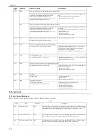
Code
Name
Sensor No.
Description
0104
Pickup Delay Jam
SR11
After execution of a pickup retry, the registration sensor (SR11) does not detect the leading edge of
paper within a specific period of time. Or after the duplex drive solenoid (SL1) is on, the registration
sensor (SR11) does not detect the leading edge of paper within a specific period of time.
0208
Pickup Stationary Jam
SR11
After the registration sensor (SR11) has detected the leading edge of paper, the registration sensor
(SR11) does not detect the trailing edge of paper within a specific period of time.
010c
Delivery Sensor Delay Jam
SR5
After the registration sensor (SR11) has detected the leading edge of paper, the delivery sensor
(SR5) does not detect the leading edge of paper within a specific period of time.
Display
Code
Detail Code
Main Cause/Symptom
Countermeasure
Summary of Contents for iR1020 Series
Page 1: ...Sep 1 2008 Service Manual iR1020 1021 1024 1025 Series ...
Page 2: ......
Page 6: ......
Page 17: ...Chapter 1 Introduction ...
Page 18: ......
Page 20: ......
Page 49: ...Chapter 1 1 29 ...
Page 50: ......
Page 51: ...Chapter 2 Installation ...
Page 52: ......
Page 54: ......
Page 61: ...Chapter 2 2 7 ...
Page 62: ......
Page 63: ...Chapter 3 Basic Operation ...
Page 64: ......
Page 66: ......
Page 73: ...Chapter 3 3 7 ...
Page 74: ......
Page 75: ...Chapter 4 Original Exposure System ...
Page 76: ......
Page 78: ......
Page 87: ...Chapter 5 Laser Exposure ...
Page 88: ......
Page 90: ......
Page 94: ......
Page 95: ...Chapter 6 Image Formation ...
Page 96: ......
Page 98: ......
Page 103: ...Chapter 7 Pickup Feeding System ...
Page 104: ......
Page 106: ......
Page 120: ......
Page 121: ...Chapter 8 Fixing System ...
Page 122: ......
Page 124: ......
Page 135: ...Chapter 9 External and Controls ...
Page 136: ......
Page 138: ......
Page 151: ...Chapter 10 Original Feeding System ...
Page 152: ......
Page 154: ......
Page 156: ...Chapter 10 10 2 M2001 ADF motor Symbol Name ...
Page 170: ......
Page 171: ...Chapter 11 e maintenance imageWARE Remote ...
Page 172: ......
Page 174: ......
Page 184: ......
Page 185: ...Chapter 12 Maintenance and Inspection ...
Page 186: ......
Page 188: ......
Page 190: ......
Page 191: ...Chapter 13 Standards and Adjustments ...
Page 192: ......
Page 194: ......
Page 201: ...Chapter 14 Correcting Faulty Images ...
Page 202: ......
Page 204: ......
Page 214: ......
Page 215: ...Chapter 15 Self Diagnosis ...
Page 216: ......
Page 218: ......
Page 224: ......
Page 225: ...Chapter 16 Service Mode ...
Page 226: ......
Page 230: ......
Page 232: ...Chapter 16 16 2 Makes various status checks such as contact sensor sensor and print status ...
Page 278: ......
Page 279: ...Chapter 17 Upgrading ...
Page 280: ......
Page 282: ......
Page 297: ...Chapter 18 Service Tools ...
Page 298: ......
Page 299: ...Contents Contents 18 1 Service Tools 18 1 18 1 1 Special Tools 18 1 ...
Page 300: ......
Page 302: ......
Page 303: ...Sep 1 2008 ...
Page 304: ......


