COPYRIGHT© 2001 CANON INC.
2000 2000 2000 2000
CANON iR105 REV.0 JULY 2001
CHAPTER 2 NEW FUNCTIONS
2-118
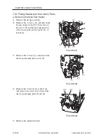
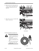
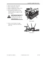
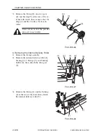
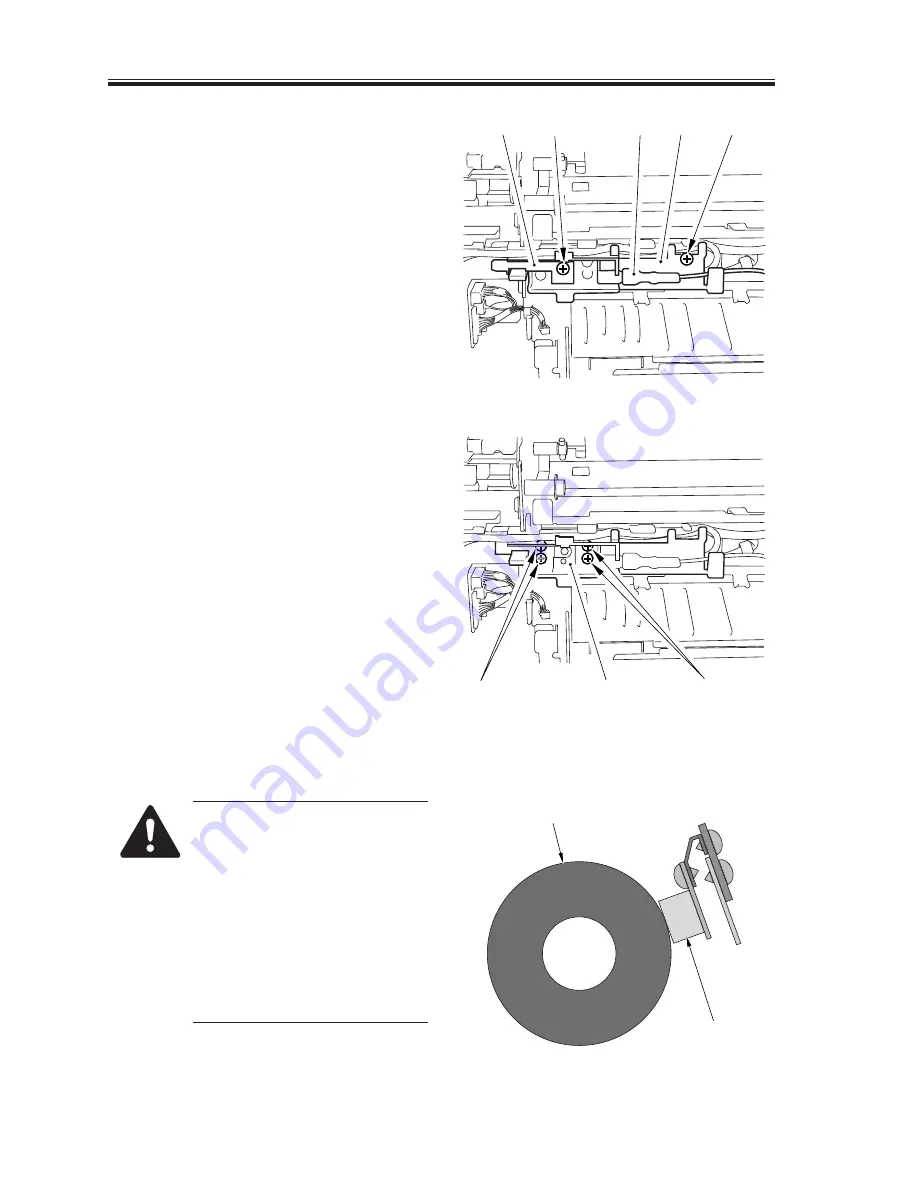
3) Remove the faston [1], and remove the
2 screws [2]; then, detach the electrode
assembly [3] and the thermal switch
holder [4].
F02-709-06
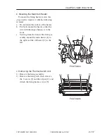
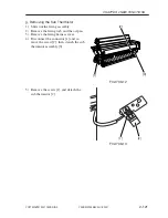
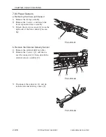
4) Remove the 4 screws [1], and detach the
thermal switch unit [2].
F02-709-07
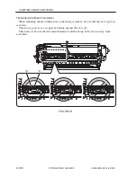
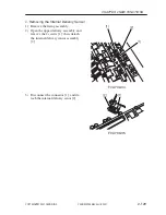
d. Mounting the Thermal Switch Unit
• When mounting the thermal
switch [1], be sure that it is in
contact with the fixing roller
[2] as shown.
• The thermal switch must be
replaced as the thermal switch
unit.
• Do not use again the thermal
switch wolse contact point
become open.
F02-709-08
[3]
[2]
[2]
[4]
[1]
[1]
[1]
[2]
[2]
[1]
Summary of Contents for iR105 Series
Page 547: ...COPYRIGHT 2001 CANON INC 2000 2000 2000 2000 CANON iR105 REV 0 JULY 2001 APPENDIX ...
Page 561: ...Service Mode COPYRIGHT 2001 CANON INC 2000 CANON iR105 REV 0 JULY 2001 ...
Page 691: ...Error Code COPYRIGHT 2001 CANON INC 2000 CANON iR105 REV 0 JULY 2001 ...
Page 727: ......
Page 731: ......
Page 737: ......
Page 739: ......
Page 745: ......
Page 749: ......
Page 757: ......
Page 761: ......
Page 765: ......
Page 769: ......
Page 775: ......
Page 799: ......
Page 817: ......
Page 827: ......
Page 833: ......
Page 839: ......
Page 845: ......
Page 873: ......
Page 877: ......
Page 887: ......
Page 891: ......
Page 901: ......
Page 905: ......
Page 909: ......
Page 917: ......
Page 921: ......
Page 925: ......
Page 931: ......
Page 939: ......
Page 943: ......
Page 951: ......
Page 1002: ......
Page 1012: ...C 10 COPYRIGHT C 2001 CANON INC STANDARD FASTENERS REV 0 FEB 1992 ...
Page 1029: ...PRINTED IN U S A IMPRIME AU U S A This publication is printed on 100 recycled paper ...


