COPYRIGHT© 2001 CANON INC.
2000 2000 2000 2000
CANON iR105 REV.0 JULY 2001
CHAPTER 2 NEW FUNCTIONS
2-172
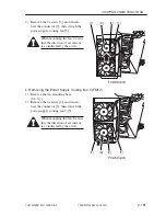
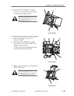
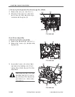
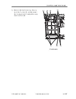
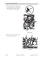
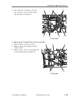
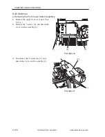
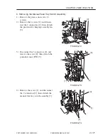
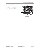
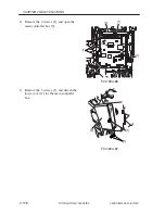
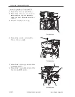
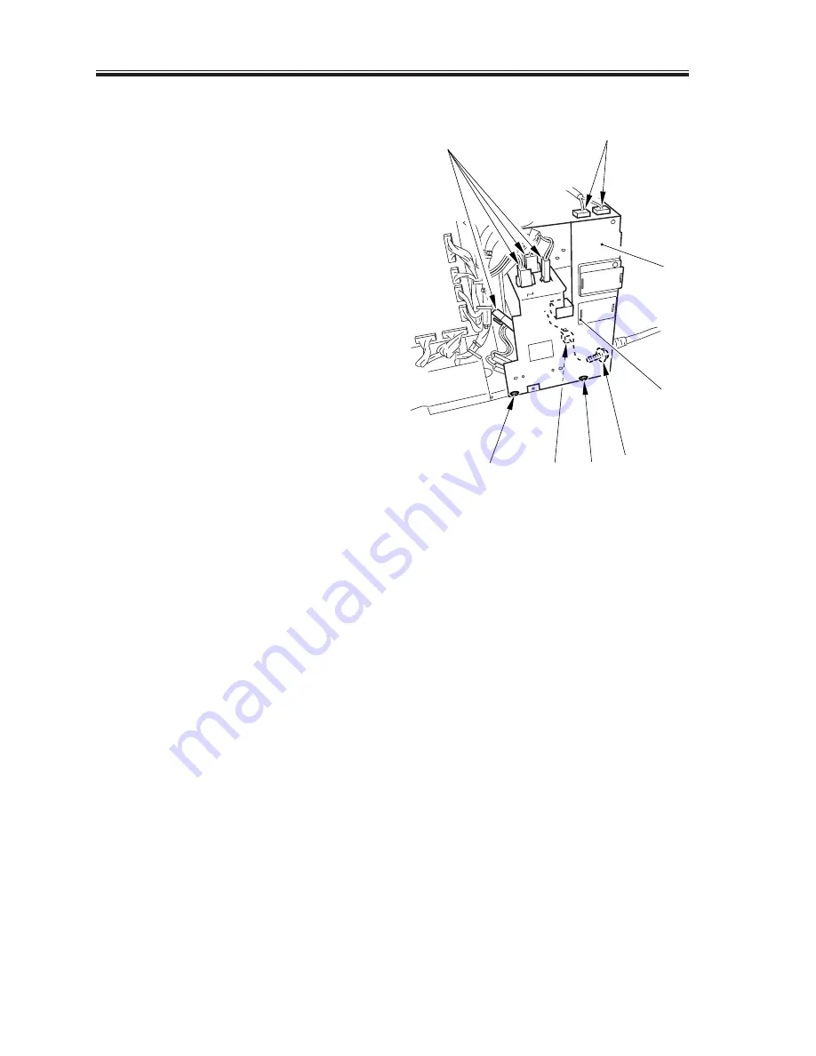
c. Removing the Drum Heater Switch Assembly
1) Remove the rear cover. (See 8.4.1.e.)
2) Remove the left lower cover. (4 screws)
3) Remove the 3 screws [1], and discon-
nect the 7 connectors [2]; then, de-
tached power cord base [3]. thereafter,
free the fixing claw to detach the drum
heat switch [4].
F02-804-75
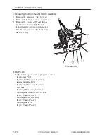
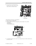
8.4.6 PCBs
For the following, see their appropriate sections:
• transformer PCB
(2 “Original Exposure System”)
• reader controller PCB
(2 “Original Exposure System”)
• hard disk
(3 “Image Processing System”)
• control panel controller (CPU) PCB
(8.4.2 “Control Panel”)
• control panel inverter PCB
(8.4.2 “Control Panel”)
control panel PCB
(8.4.2 “Control Panel”)
[2]
[2]
[2]
[1]
[1]
[1]
[3]
[4]
Summary of Contents for iR105 Series
Page 547: ...COPYRIGHT 2001 CANON INC 2000 2000 2000 2000 CANON iR105 REV 0 JULY 2001 APPENDIX ...
Page 561: ...Service Mode COPYRIGHT 2001 CANON INC 2000 CANON iR105 REV 0 JULY 2001 ...
Page 691: ...Error Code COPYRIGHT 2001 CANON INC 2000 CANON iR105 REV 0 JULY 2001 ...
Page 727: ......
Page 731: ......
Page 737: ......
Page 739: ......
Page 745: ......
Page 749: ......
Page 757: ......
Page 761: ......
Page 765: ......
Page 769: ......
Page 775: ......
Page 799: ......
Page 817: ......
Page 827: ......
Page 833: ......
Page 839: ......
Page 845: ......
Page 873: ......
Page 877: ......
Page 887: ......
Page 891: ......
Page 901: ......
Page 905: ......
Page 909: ......
Page 917: ......
Page 921: ......
Page 925: ......
Page 931: ......
Page 939: ......
Page 943: ......
Page 951: ......
Page 1002: ......
Page 1012: ...C 10 COPYRIGHT C 2001 CANON INC STANDARD FASTENERS REV 0 FEB 1992 ...
Page 1029: ...PRINTED IN U S A IMPRIME AU U S A This publication is printed on 100 recycled paper ...

