COPYRIGHT© 2001 CANON INC.
2000 2000 2000 2000
CANON iR105 REV.0 JULY 2001
CHAPTER 6 TROUBLESHOOTING
6-49
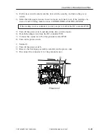
3) Fit the door switch actuator into the door switch assembly, and turn on the power
switch.
4) Make the following selections in service mode, and check to see if the reading is be-
tween 0 and 30 during initial rotation: COPIER>DISPLAY>DPOT>DPOT-K.
If the reading is not as indicated, you may suspect a fault in the DC controller PCB.
5) Turn off the power switch, and detach the door switch actuator.
6) Detach the jumper wire from the DC controller PCB.
7) Connect the connector to J3 of the potential control PCB.
8) Turn on the power switch.
2. Method 2
1) Turn off the power switch.
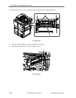
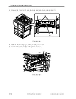
2) Remove the developing assembly, and slide out the process unit.
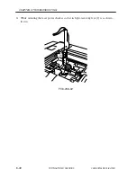
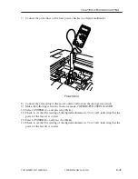
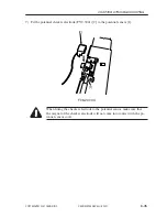
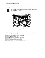
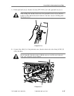
3) Disconnect the connector [1] of the potential sensor.
F06-207-07
[1]
Summary of Contents for iR105 Series
Page 547: ...COPYRIGHT 2001 CANON INC 2000 2000 2000 2000 CANON iR105 REV 0 JULY 2001 APPENDIX ...
Page 561: ...Service Mode COPYRIGHT 2001 CANON INC 2000 CANON iR105 REV 0 JULY 2001 ...
Page 691: ...Error Code COPYRIGHT 2001 CANON INC 2000 CANON iR105 REV 0 JULY 2001 ...
Page 727: ......
Page 731: ......
Page 737: ......
Page 739: ......
Page 745: ......
Page 749: ......
Page 757: ......
Page 761: ......
Page 765: ......
Page 769: ......
Page 775: ......
Page 799: ......
Page 817: ......
Page 827: ......
Page 833: ......
Page 839: ......
Page 845: ......
Page 873: ......
Page 877: ......
Page 887: ......
Page 891: ......
Page 901: ......
Page 905: ......
Page 909: ......
Page 917: ......
Page 921: ......
Page 925: ......
Page 931: ......
Page 939: ......
Page 943: ......
Page 951: ......
Page 1002: ......
Page 1012: ...C 10 COPYRIGHT C 2001 CANON INC STANDARD FASTENERS REV 0 FEB 1992 ...
Page 1029: ...PRINTED IN U S A IMPRIME AU U S A This publication is printed on 100 recycled paper ...

