COPYRIGHT © 2002 CANON INC. CANON FAX BOARD REV.0 MAR. 2002
2 - 4
CHAPTER 2 BASIC OPERATION
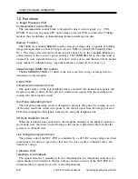
1.4 Functions
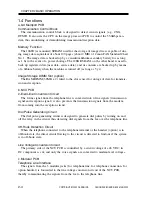
a.G3 Multiport PCB
Communication Control Block
The communication control block is designed to detect circuit signals (e.g., CNG,
DTMF). It also uses the CPU on the image processor PCB to control the 33.6Kbps mo-
dem, thus modulating or demodulating transmission/reception data.
Memory Function
The 16MB (as mounted) SDRAM used for the storage of image data is capable of stor-
ing image data equivalent of about 100 pages (about 2 MB) of Canon FAX Standard Chart
No. 1. The image data is backed up by a vanadium lithium secondary battery for as long
as 1 hr in the event of a power shortage. The 128KB SRAM, on the other hand, is used to
back up registered data (user data, service data), and its contents are backed up by means
of a lithium battery when the machine is turned off (as long as 5 yr).
Image Storage DIMM Slot (option)
The RAM-DIMM (32MB x 2) fitted to the slot is used for storage of data for transmis-
sion and reception.
b. NCU PCB
2-line/4-line Conversion Circuit
The 2-line signal from the telephone line is converted into 4-line signals (transmission
signal and reception signal): it also prevents the transmission signals from the modem
from coming into the reception circuit.
Dial Pulse Generating Circuit
The dial pulse generating circuit is designed to generate dial pulses by turning on and
off the relay in the circuit, thus detecting dial signals from the fax over the telephone line.
Off-Hook Detection Circuit
When the telephone connected to the telephone terminal or the handset (option) is in
off-hook state, the direct circuit flowing to the circuit is detected to find out if the system
is in off-hook state.
Line Voltage Conversion Circuit
The primary side of the NCU PCB is controlled by a circuit voltage of +48 VDC; its
DC component is cut, and only the voice signals are converted to modem-level voltages.
c. Modular PCB
Telephone Line Interface
The signals from the 3 modular jacks (for telephone line, for telephone connection, for
option handset) is forwarded to the line voltage conversion circuit of the NCU PCB,
thereby communicating the signals from the fax to the telephone line.
Summary of Contents for iR1600 Series
Page 24: ......
Page 26: ......
Page 96: ......
Page 110: ......
Page 112: ......
Page 144: ......
Page 146: ......
Page 158: ......
Page 160: ......
Page 182: ......
Page 216: ......
Page 218: ......
Page 248: ......
Page 250: ......
Page 284: ......
Page 298: ......
Page 300: ......
Page 312: ......
Page 314: ......
Page 366: ......
Page 368: ......
Page 378: ......
Page 604: ......
Page 606: ......
Page 648: ......
Page 650: ......
Page 652: ......
Page 656: ......
Page 660: ......
Page 665: ...COPYRIGHT 2002 CANON INC CANON FAX BOARD REV 0 MAR 2002 CHAPTER 1 INTRODUCTION...
Page 666: ......
Page 671: ...COPYRIGHT 2002 CANON INC CANON FAX BOARD REV 0 MAR 2002 CHAPTER 2 BASIC OPERATION...
Page 672: ......
Page 679: ...COPYRIGHT 2002 CANON INC CANON FAX BOARD REV 0 MAR 2002 CHAPTER 3 TROUBLESHOOTING...
Page 680: ......
Page 688: ......
Page 694: ......
Page 696: ......
Page 702: ......
Page 704: ......
Page 712: ......
Page 722: ......
Page 732: ......
Page 734: ......
Page 736: ......

