COPYRIGHT © 2001 CANON INC.
2000 2000 2000 2000
CANON iR2200/iR2800/iR3300 REV.0 MAR. 2001
CHAPTER 3 IMAGE PROCESSING SYSTEM
3-1 R
1 Outline
The major functions of the image processing system are as follows:
[1] CCD (image sensor)
Number of lines: 1
Number of pixels: 7450
Size of pixel: 4.7 × 4.7 µm
[2] Shading Correction
Shading adjustment: executed in service mode
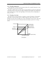
Shading correction: executed for each copy
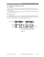
[3] Auto Density Adjustment (AE)
Executed for each line in main scanning direction.
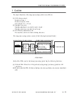
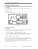
The image processing system consists of the following functional blocks:
F03-100-01
Each of the PCBs used in the image processing system has the following functions:
[1] CCD/AP PCB. Drives the CCD, performs analog image processing, performs A/D
conversion.
[2] Reader controller PCB. Performs shading correction, performs auto density adjustment
(AE).
CCD
CCD
PCB
Reader controller PCB
A/D
conve
-rsion
Shading processing
Analog
image
processing
Analog image processing block
Controller unit
Digital image processing block
Auto density
correction (AE)
Summary of Contents for iR2200 Series
Page 8: ......
Page 12: ......
Page 30: ......
Page 32: ......
Page 54: ......
Page 86: ......
Page 90: ......
Page 94: ......
Page 96: ......
Page 124: ......
Page 142: ......
Page 152: ......
Page 160: ......
Page 168: ......
Page 178: ......
Page 180: ......
Page 222: ......
Page 224: ......
Page 278: ......
Page 280: ......
Page 298: ......
Page 300: ......
Page 324: ......
Page 368: ......
Page 386: ......
Page 388: ......
Page 404: ......
Page 414: ......
Page 416: ......
Page 422: ......
Page 424: ......
Page 434: ......
Page 436: ......
Page 440: ......
Page 468: ......
Page 473: ......
Page 550: ......
Page 552: ......
Page 658: ......
Page 704: ......
Page 706: ......
Page 754: ......
Page 756: ......
Page 760: ......

