COPYRIGHT © 2001 CANON INC.
2000 2000 2000 2000
CANON iR2200/iR2800/iR3300 REV.0 MAR. 2001
CHAPTER 2 SEQUENCE OF OPERATIONS
2-1 P
1 Basic Operations
1.1 Functional Construction
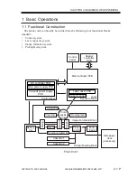
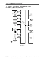
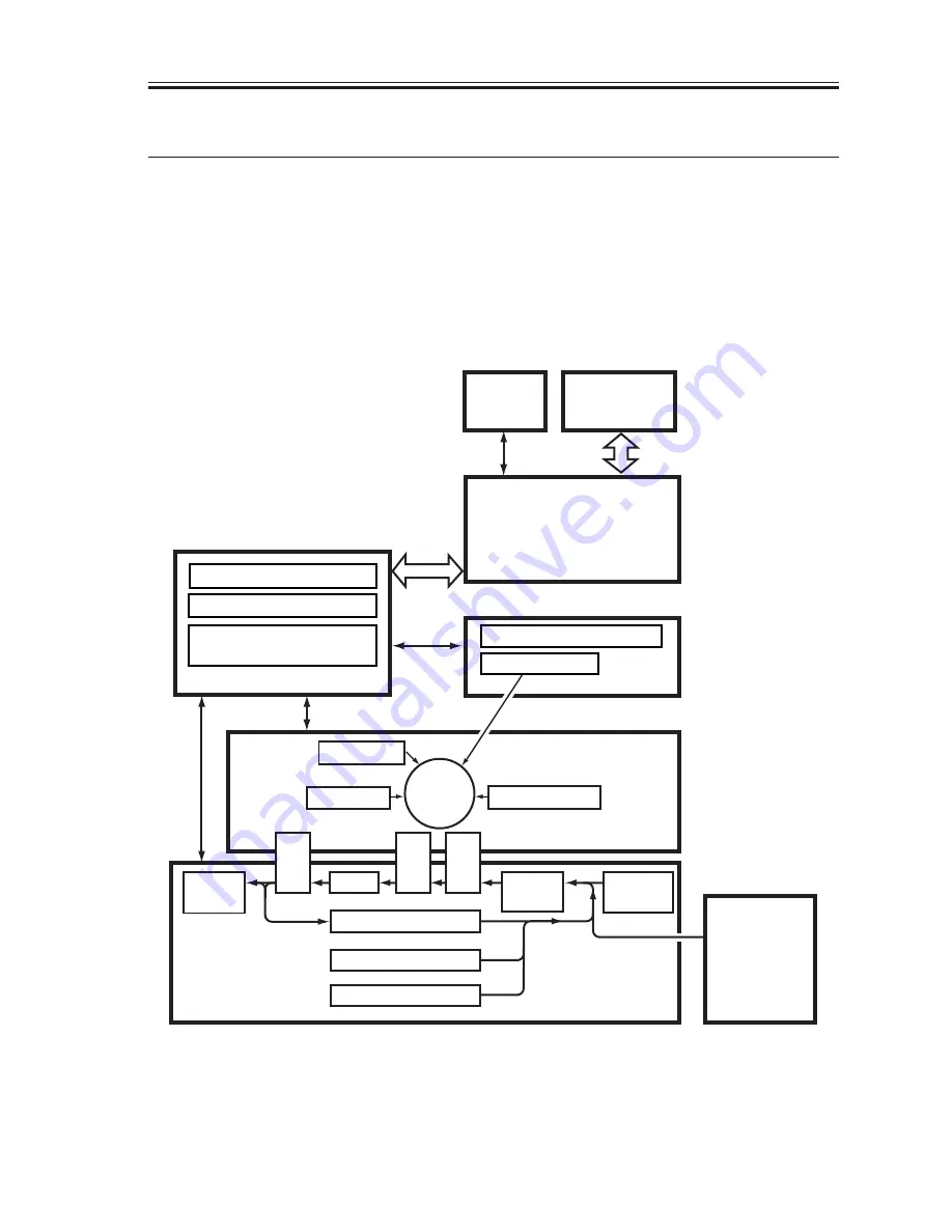
The printer unit can broadly be divided into the following four functional blocks
(shaded):
•
Control system
•
Laser exposure system
•
Image formation system
•
Pickup/feed system
F02-101-01
Control
panel
DC controller PCB
Main power supply PCB
Conposit power supply
PCB
Main controller PCB
Laser driver PCB
Laser scanner
Charging
Development
T
ransf
er
Pickup
control
Multi-
feeder
Cleaning
Duplexing assembly
Cassette 1
Delivery
tray
Feeding
Separ
ation
Fixing
Photo-
sensitive
drum
Cassette 2
Laser
Exposure Block
Pickup/Feeding Block
Image Formation Block
Control Block
Reader
controller
PCB
Side paper
deck
(accessory)
Summary of Contents for iR2200 Series
Page 8: ......
Page 12: ......
Page 30: ......
Page 32: ......
Page 54: ......
Page 86: ......
Page 90: ......
Page 94: ......
Page 96: ......
Page 124: ......
Page 142: ......
Page 152: ......
Page 160: ......
Page 168: ......
Page 178: ......
Page 180: ......
Page 222: ......
Page 224: ......
Page 278: ......
Page 280: ......
Page 298: ......
Page 300: ......
Page 324: ......
Page 368: ......
Page 386: ......
Page 388: ......
Page 404: ......
Page 414: ......
Page 416: ......
Page 422: ......
Page 424: ......
Page 434: ......
Page 436: ......
Page 440: ......
Page 468: ......
Page 473: ......
Page 550: ......
Page 552: ......
Page 658: ......
Page 704: ......
Page 706: ......
Page 754: ......
Page 756: ......
Page 760: ......

