COPYRIGHT © 2001 CANON INC.
2000 2000 2000 2000
CANON iR2200/iR2800/iR3300 REV.0 MAR. 2001
CHAPTER 4 IMAGE FORMATION SYSTEM
4-14 P
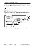
4 Controlling the Separation Static Eliminator Bias
4.1 Outline
Part 2>Chapter 5>8.3 “Static Eliminator Separation Method”
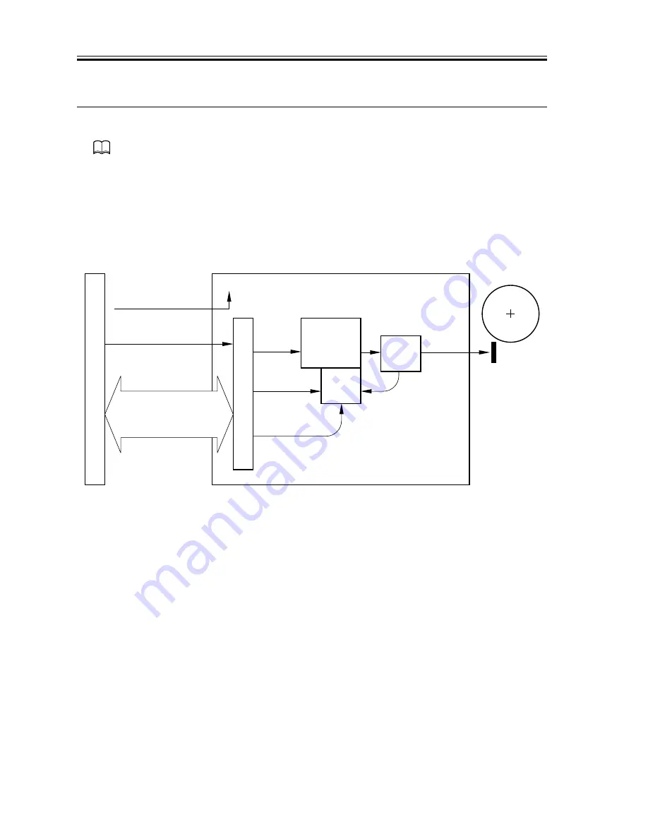
The machine uses a static eliminator for separation. A DC bias is applied to the static
eliminator; the following are items of control:
[1] Turning on/off the bias
[2] Controlling the bias to a specific voltage level
[3] Controlling the output to suit paper type and reading by the environment sensor (humid-
ity)
F04-401-01
DC controller PCB
Static
eliminator bias
enable signal
Static eliminator bias
mode signal
Static
eliminator
bias output
J301
-B3
J136
-B10
J135
J301
-A3
-A1
J136
-A10
-A12
24 VDC input from
main power supply
Composite power supply PCB
PW
-CPU
Transformer
drive signal
J132
Serial communication
Print/standby mode signal
Static eliminator bias
mode signal
High-voltage
main
transformer
(T504)
Separation
static eliminator
Output
control
Voltage
detection
Voltage
level
+24V
Static
eliminator bias
output ON signal
Photosensitive
drum
Summary of Contents for iR2200 Series
Page 8: ......
Page 12: ......
Page 30: ......
Page 32: ......
Page 54: ......
Page 86: ......
Page 90: ......
Page 94: ......
Page 96: ......
Page 124: ......
Page 142: ......
Page 152: ......
Page 160: ......
Page 168: ......
Page 178: ......
Page 180: ......
Page 222: ......
Page 224: ......
Page 278: ......
Page 280: ......
Page 298: ......
Page 300: ......
Page 324: ......
Page 368: ......
Page 386: ......
Page 388: ......
Page 404: ......
Page 414: ......
Page 416: ......
Page 422: ......
Page 424: ......
Page 434: ......
Page 436: ......
Page 440: ......
Page 468: ......
Page 473: ......
Page 550: ......
Page 552: ......
Page 658: ......
Page 704: ......
Page 706: ......
Page 754: ......
Page 756: ......
Page 760: ......


