COPYRIGHT © 2001 CANON INC.
2000 2000 2000 2000
CANON iR2200/iR2800/iR3300 REV.0 MAR. 2001
CHAPTER 4 IMAGE FORMATION SYSTEM
4-38 P
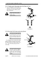
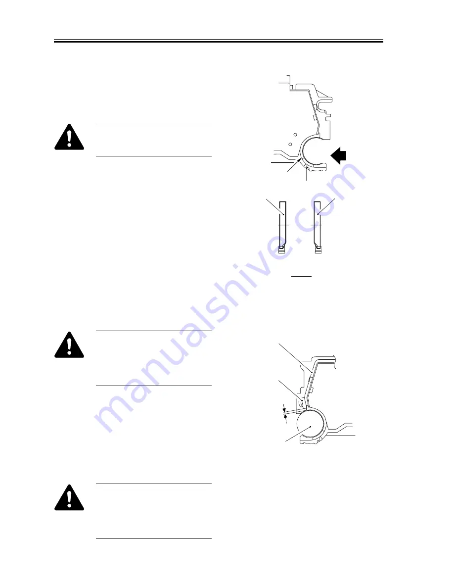
9.5.7 Positioning the Developing Assembly Magnetic Seal
1) The front magnetic seal [1] and the rear
magnetic seal [2] must be butted against
the opening [3] (stop reference) when
they are mounted.
Check to make sure that the
magnetic seal is in firm contact
with the casing.
F04-905-14
9.5.8 Mounting the Developing Assembly Blade
The blade [1] and the blade base
[2] of the blade base unit are ad-
justed to a high accuracy at the
factory. Do not disassemble the
unit.
If you happen to have removed the blade,
adjust its position so that the gap between
the blade and the developing cylinder [3] is
0.21 ± 0.03 mm using a gap gauge (CK-
0057-000).
F04-905-15
The surface of the developing
cylinder is highly susceptible to
scratches. Be sure to fit the gap
gauge on ends of the developing
cylinder.
A
A
[1]
[2]
[3]
[1] ([2])
[1]
[2]
[3]
0.21±0.03mm
Summary of Contents for iR2200 Series
Page 8: ......
Page 12: ......
Page 30: ......
Page 32: ......
Page 54: ......
Page 86: ......
Page 90: ......
Page 94: ......
Page 96: ......
Page 124: ......
Page 142: ......
Page 152: ......
Page 160: ......
Page 168: ......
Page 178: ......
Page 180: ......
Page 222: ......
Page 224: ......
Page 278: ......
Page 280: ......
Page 298: ......
Page 300: ......
Page 324: ......
Page 368: ......
Page 386: ......
Page 388: ......
Page 404: ......
Page 414: ......
Page 416: ......
Page 422: ......
Page 424: ......
Page 434: ......
Page 436: ......
Page 440: ......
Page 468: ......
Page 473: ......
Page 550: ......
Page 552: ......
Page 658: ......
Page 704: ......
Page 706: ......
Page 754: ......
Page 756: ......
Page 760: ......

