COPYRIGHT © 2001 CANON INC.
2000 2000 2000 2000
CANON iR2200/iR2800/iR3300 REV.0 MAR. 2001
CHAPTER 1 GENERAL DESCRIPTION
1-13 S
3 System Configuration
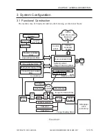
3.1 Functional Construction
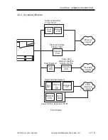
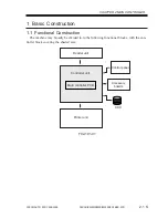
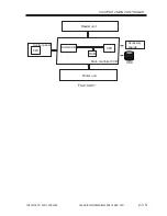
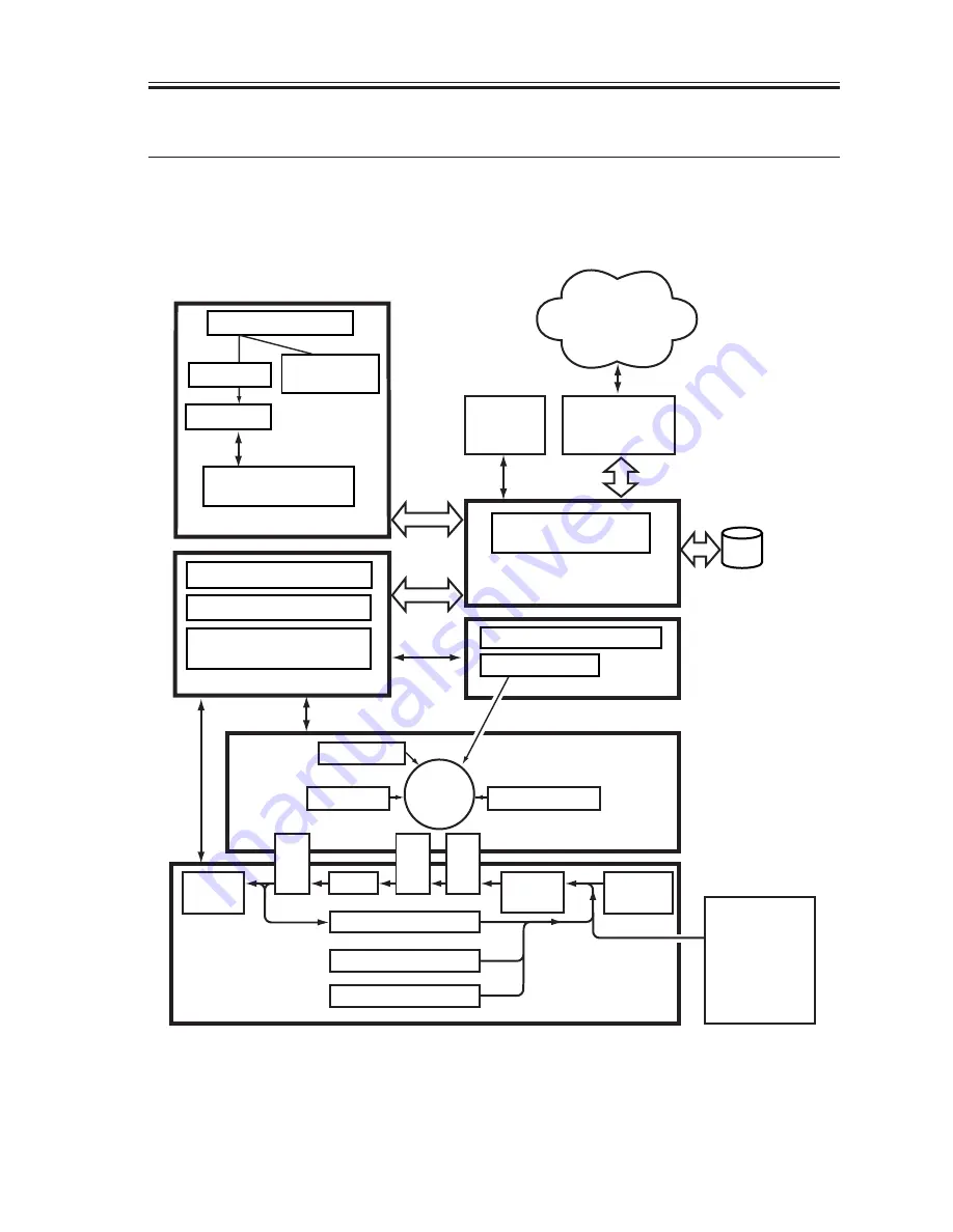
The machine may be broadly divided into the following six functional blocks:
F01-301-01
Control
panel
DC controller PCB
Main power supply PCB
Conposit power supply
PCB
Main controller PCB
CCD PCB
Laser driver PCB
Reader controller
PCB
Laser scanner
Original
Original
illumination
Charging
Development
T
ransf
er
Pickup
control
Multi-
feeder
Cleaning
Duplexing assembly
Cassette 1
Delivery
tray
Feeding
Separ
ation
Fixing
Photo-
sensitive
drum
Cassette 2
HDD
Original Exposure Block
System control/
Image Processing Block
Laser
Exposure Block
Pickup/Feeding Block
Image Formation Block
Control Block
Various
accessory
boards
Side paper
deck
(accessory)
Optical path
Various
networks or public
telephone
network
Summary of Contents for iR2200 Series
Page 8: ......
Page 12: ......
Page 30: ......
Page 32: ......
Page 54: ......
Page 86: ......
Page 90: ......
Page 94: ......
Page 96: ......
Page 124: ......
Page 142: ......
Page 152: ......
Page 160: ......
Page 168: ......
Page 178: ......
Page 180: ......
Page 222: ......
Page 224: ......
Page 278: ......
Page 280: ......
Page 298: ......
Page 300: ......
Page 324: ......
Page 368: ......
Page 386: ......
Page 388: ......
Page 404: ......
Page 414: ......
Page 416: ......
Page 422: ......
Page 424: ......
Page 434: ......
Page 436: ......
Page 440: ......
Page 468: ......
Page 473: ......
Page 550: ......
Page 552: ......
Page 658: ......
Page 704: ......
Page 706: ......
Page 754: ......
Page 756: ......
Page 760: ......


