COPYRIGHT © 2001 CANON INC.
2000 2000 2000 2000
CANON iR2200/iR2800/iR3300 REV.0 MAR. 2001
CHAPTER 5 PICK-UP/FEEDING SYSTEM
5-35 P
8 Controlling the Pickup Assembly Motor
8.1 Pickup Assembly Motor
The pickup assembly motor system consists of six stepping motors of 2-phase magnetic
excitation type.
Each motor is supplied with power by the motor driver PCB, and is turned on/off and ro-
tated clockwise or counterclockwise by pulse signals from the DC controller PCB.
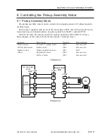
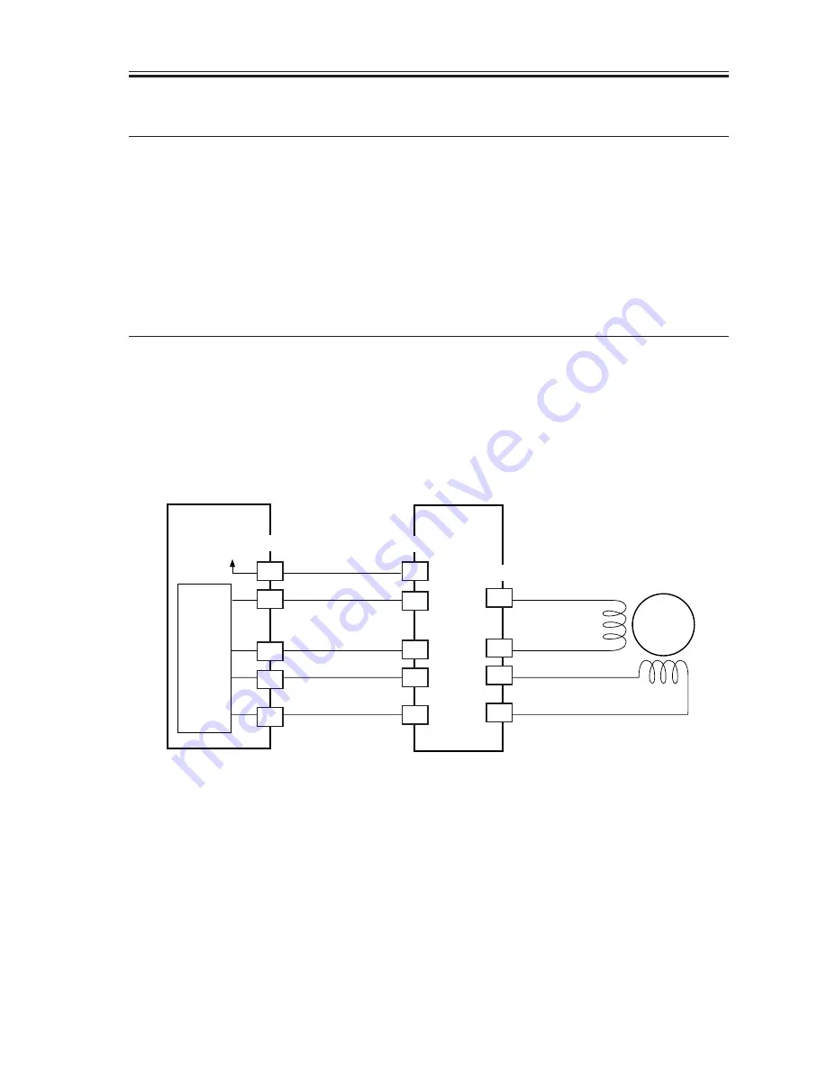
T05-801-01 shows the motors used in the pickup assembly and F05-801-01 shows a
block diagram of the control circuit for the cassette 1/2 pickup motor:
Location
Motor name
Notation
Error detection
Pickup system
Cassette 1/2 pickup motor
(M2)
Jam occurred
Vertical path system
Duplex motor
(M6)
Jam occurred
Duplex system
Duplex registration motor
(M3)
E051
Others
Registration moter
(M9)
Jam occurred
Delivery moter
(M5)
Jam occurred
T05-801-01
F05-801-01
Feeder driver
PCB
M2
A6
18
A7
J302
3
4
1
2
J1602
DC controller
PCB
PIO
(IC303)
A
A*
B
B*
A8
A9
13
12
J1601
11
10
+24V
A1
Summary of Contents for iR2200 Series
Page 8: ......
Page 12: ......
Page 30: ......
Page 32: ......
Page 54: ......
Page 86: ......
Page 90: ......
Page 94: ......
Page 96: ......
Page 124: ......
Page 142: ......
Page 152: ......
Page 160: ......
Page 168: ......
Page 178: ......
Page 180: ......
Page 222: ......
Page 224: ......
Page 278: ......
Page 280: ......
Page 298: ......
Page 300: ......
Page 324: ......
Page 368: ......
Page 386: ......
Page 388: ......
Page 404: ......
Page 414: ......
Page 416: ......
Page 422: ......
Page 424: ......
Page 434: ......
Page 436: ......
Page 440: ......
Page 468: ......
Page 473: ......
Page 550: ......
Page 552: ......
Page 658: ......
Page 704: ......
Page 706: ......
Page 754: ......
Page 756: ......
Page 760: ......

