COPYRIGHT © 2001 CANON INC.
2000 2000 2000 2000
CANON iR2200/iR2800/iR3300 REV.0 MAR. 2001
CHAPTER 6 FIXING SYSTEM
6-9 P
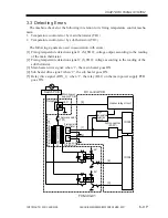
3.3 Detecting Errors
The machine checks for the following in relation to its fixing temperature control mecha-
nism:
1. Temperature control error by main thermistor (TH1)
2. Temperature control error by sub thermistor (TH2)
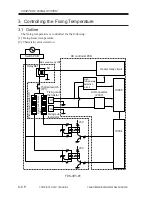
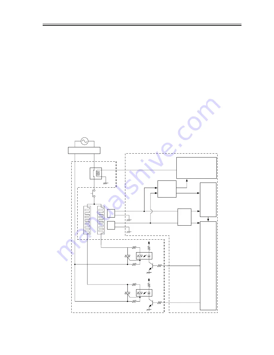
The following signals are used in association with errors:
[1] Fixing temperature detection signal 1 (M_TH2): voltage output according to the reading
of the main thermistor.
[2] Fixing temperature detection signal 2 (S_TH2): voltage according to the reading of the
sub thermistor.
[3] Main heater drive signal: when ‘1’, the main heater goes ON.
[4] Sub heater drive signal: when ‘2’, the sub heater goes ON.
[5] Relay drive signal (RLY_1): when ‘1’, the relay (RL1) on the main power supply PCB
goes ON.
F06-303-01
+5V
+5V
+5V
TH1
Fixing main
thermistor
TH2
Fixing sub
thermistor
Heater relay circuit
A/D converter
(200V)
Thermal switch
(TP1)
Fixing main heater (H1)
Fixing sub heater (H2)
IC300
IC334
Switch PCB
Relay
RL1
DC control PCB
Main power
supply PCB
[1]
[5]
[2]
[3]
[4]
High-
temperature
detection
circuit
Summary of Contents for iR2200 Series
Page 8: ......
Page 12: ......
Page 30: ......
Page 32: ......
Page 54: ......
Page 86: ......
Page 90: ......
Page 94: ......
Page 96: ......
Page 124: ......
Page 142: ......
Page 152: ......
Page 160: ......
Page 168: ......
Page 178: ......
Page 180: ......
Page 222: ......
Page 224: ......
Page 278: ......
Page 280: ......
Page 298: ......
Page 300: ......
Page 324: ......
Page 368: ......
Page 386: ......
Page 388: ......
Page 404: ......
Page 414: ......
Page 416: ......
Page 422: ......
Page 424: ......
Page 434: ......
Page 436: ......
Page 440: ......
Page 468: ......
Page 473: ......
Page 550: ......
Page 552: ......
Page 658: ......
Page 704: ......
Page 706: ......
Page 754: ......
Page 756: ......
Page 760: ......

