COPYRIGHT © 2001 CANON INC.
2000 2000 2000 2000
CANON iR2200/iR2800/iR3300 REV.0 MAR. 2001
CONTENTS
T 1
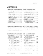
Contents
CHAPTER 1 MAINTENANCE AND INSPECTION
CHAPTER 2 IMAGE ADJUSTMENT BASIC PROCEDURE
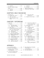
1
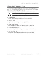
Periodically Replaced Parts ........... 1-1T
1.1
Reader Unit ............................. 1-1T
1.2
Printer Unit ............................. 1-1T
1.3
Side Paper Deck ...................... 1-1T
1.4
Cassette Feeding unit .............. 1-1T
1.5
Inner 2-Way Tray .................... 1-1T
2
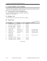
Consumables and Durables ........... 1-2T
2.1
Checking the Time of
Replacement ............................. 1-2T
2.2
Reader Unit .............................. 1-2T
2.3
Printer Unit ............................... 1-2T
2.4
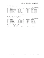
Side Paper Deck ....................... 1-3T
2.5
Cassette Feeding Unit ............... 1-3T
2.6
Inner 2-Way Tray-A1 ............... 1-3T
3
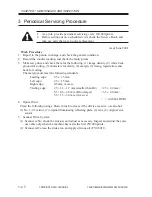
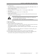
Periodical Servicing Procedure ....... 1-4T
4
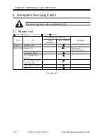
Scheduled Servicing Chart .............. 1-6T
4.1
Reader Unit .............................. 1-6T
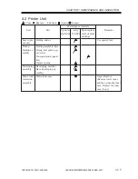
4.2
Printer Unit ............................... 1-7T
5
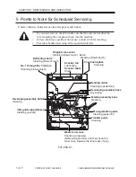
Points to Note for Scheduled
Servicing ......................................... 1-8T
6
Cleaning the Bottom of the
Developing Assembly ..................... 1-9T
6.1
Cleaning the Bottom of the
Developing Assembly .............. 1-9T
1
Making lnitial Checks ................... 2-1T
2
Checking the Scanner Side ........... 2-1T
3
Checking the Printer Side (1/3) ..... 2-2T
4
Checking the Printer Side (2/3) ..... 2-2T
5
Checking the Printer Side (3/3) ..... 2-2T
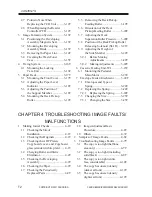
CHAPTER 3 STANDARDS AND ADJUSTMENTS
1
Image Adjustments ........................ 3-1T
1.1
Standards of Image Position ... 3-1T
1.2
Checking the Image Position .. 3-2T
1.3
Adjusting Left/Right
lamge Margin ........................... 3-3T
1.3.1
Adjusting the Registration
for the Cassette Rear Front . 3-3T
1.3.2
Adjusting the Registration
for the Multifeeder
Rear Front .......................... 3-4T
1.3.3
Adjusting the Registration
for the Deck ....................... 3-4T
1.3.4
Duplex Feeding Unit .......... 3-5T
1.4
Adjusting the Image Leading
Edge Margin ............................. 3-5T
1.5
Adjusting the Left/Right
Non-Image Width ..................... 3-5T
1.6
Adjusting the Leading Edge
Non-Image Width ..................... 3-6T
2
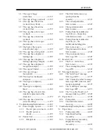
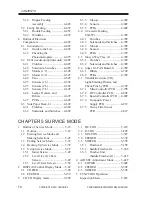
Scanning System ............................ 3-6T
2.1
After Replacing the Scanning
Lamp ........................................ 3-6T
2.2
Mounting the Motor Unit ......... 3-7T
2.3
Routing the Scanner
Drive Cable .............................. 3-8T
2.4
Adjusting the Position of the
No. 1/No. 2 Mirror Base .......... 3-9T
2.5
Mounting the Copyboard
Glass ...................................... 3-11T
2.6
Mounting the Reader Upper
Frame ..................................... 3-12T
Summary of Contents for iR2200 Series
Page 8: ......
Page 12: ......
Page 30: ......
Page 32: ......
Page 54: ......
Page 86: ......
Page 90: ......
Page 94: ......
Page 96: ......
Page 124: ......
Page 142: ......
Page 152: ......
Page 160: ......
Page 168: ......
Page 178: ......
Page 180: ......
Page 222: ......
Page 224: ......
Page 278: ......
Page 280: ......
Page 298: ......
Page 300: ......
Page 324: ......
Page 368: ......
Page 386: ......
Page 388: ......
Page 404: ......
Page 414: ......
Page 416: ......
Page 422: ......
Page 424: ......
Page 434: ......
Page 436: ......
Page 440: ......
Page 468: ......
Page 473: ......
Page 550: ......
Page 552: ......
Page 658: ......
Page 704: ......
Page 706: ......
Page 754: ......
Page 756: ......
Page 760: ......

