COPYRIGHT © 2001 CANON INC.
2000 2000 2000 2000
CANON iR2200/iR2800/iR3300 REV.0 MAR. 2001
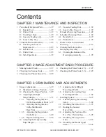
CONTENTS
T 2
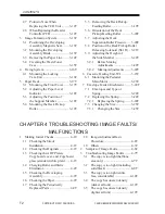
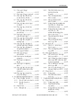
CHAPTER 4 TROUBLESHOOTING IMAGE FAULTS/
MALFUNCTIONS
1
Making Initial Checks ................... 4-1T
1.1
Checking the Site of
Installation ................................. 4-1T
1.2
Checking the Originals ............. 4-1T
1.3
Checking the ADF Platen,
Copyboard cover, and Copyboard
glass (standard white plate) .... 4-1T
1.4
Charging Roller and Static
Eliminator ................................. 4-2T
1.5
Checking the Developing
Assembly ................................. 4-2T
1.6
Checking the Paper ................... 4-2T
1.7
Checking the Periodically
Replaced Parts .......................... 4-2T
1.8
Image Adjustment Basic
Procedure ................................. 4-2T
1.9
Others ....................................... 4-3T
2
Samples of Image Faults ................. 4-6T
3
Troubleshooting Image Faults ........ 4-7T
3.1
The copy is too light (halftone
area only) .................................. 4-7T
3.2
The copy is too light (including
solid black) ............................... 4-8T
3.3
The copy is too light (entire
face, considerable) .................. 4-10T
3.4
The copy has uneven density
(darker at front) ...................... 4-12T
3.5
The copy has uneven density
(lighter at front) ...................... 4-12T
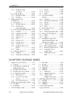
2.7
Points to Note When
Replacing the CCD Unit ......... 3-12T
2.8
When Replacing the Reader
Controller PCB ....................... 3-12T
3
Image Formation System .............. 3-13T
3.1
Positioning the Developing
Assembly Magnetic Seal ........ 3-13T
3.2
Mounting the Developing
Assembly Blade ..................... 3-13T
3.3
Removing the Paper Lint ........ 3-14T
3.4
Cleaning the Waste Toner
Case ........................................ 3-15T
4
Fixing System ............................... 3-16T
4.1
Mounting the Locking
Cam Unit ................................ 3-16T
5
Paper Deck ................................... 3-17T
5.1
Mounting the Front Cover ...... 3-17T
5.2
Adjusting the Paper Level
Indicator ................................. 3-18T
5.3
Adjusting the Position of
the Support Member ............... 3-18T
5.4
Mounting the Deck Pickup
Roller ...................................... 3-19T
5.5
Removing the Deck Pickup/
Feeding Roller ........................ 3-19T
5.6
Orientation of the Deck
Pickup/Feeding Roller ............ 3-20T
5.7
Adjusting the Deck
Separation Roller Pressure ..... 3-20T
5.8
Position of the Deck Pickup Roller
Releasing Solenoid (SL1D) .. 3-21T
5.9
Adjusting the Height of
the Side Member .................... 3-22T
5.9.1
Before Making
Adjustments ..................... 3-22T
5.9.2
Making Adjustments ........ 3-22T
6
Cassette Feeding Unit-W1 ............ 3-23T
6.1
Mounting the Pedestal
Main Motor ............................ 3-23T
7
Envelope Feeder Attachment ......... 3-24T
7.1
Envelopes and Type of
Spring ..................................... 3-24T
7.2
Replacing the Spring .............. 3-24T
7.2.1
Replacing the Spring ........ 3-24T
7.3
Changing the Size ................... 3-25T
7.3.1
Changing the Size ............ 3-25T
Summary of Contents for iR2200 Series
Page 8: ......
Page 12: ......
Page 30: ......
Page 32: ......
Page 54: ......
Page 86: ......
Page 90: ......
Page 94: ......
Page 96: ......
Page 124: ......
Page 142: ......
Page 152: ......
Page 160: ......
Page 168: ......
Page 178: ......
Page 180: ......
Page 222: ......
Page 224: ......
Page 278: ......
Page 280: ......
Page 298: ......
Page 300: ......
Page 324: ......
Page 368: ......
Page 386: ......
Page 388: ......
Page 404: ......
Page 414: ......
Page 416: ......
Page 422: ......
Page 424: ......
Page 434: ......
Page 436: ......
Page 440: ......
Page 468: ......
Page 473: ......
Page 550: ......
Page 552: ......
Page 658: ......
Page 704: ......
Page 706: ......
Page 754: ......
Page 756: ......
Page 760: ......


