COPYRIGHT © 2001 CANON INC.
2000 2000 2000 2000
CANON iR2200/iR2800/iR3300 REV.0 MAR. 2001
CHAPTER 5 SERVICE MODE
5-51 T
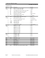
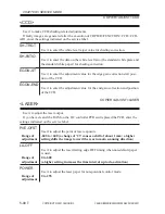
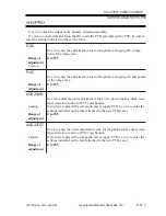
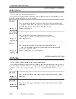
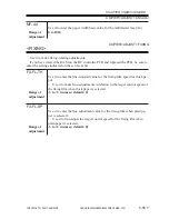
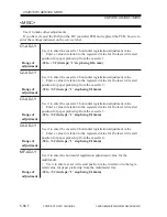
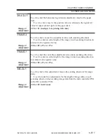
<HV-PRI>
Use it to adjust the output of the primary charging assembly.
If you have cleared the RAM on the DC controller PCB and replaced the PCB, be sure to
enter the setting indicated on the service label.
P-DC
Use it to enter the adjustment value for the primary charging DC compo-
nent of the image area.
Range of
0 to 255
adjustment
Caution
P-AC
Use it to enter the adjustment value for the primary charging AC component
of the image area.
Range of
0 to 255
adjustment
AGS-GAIN
Use it to adjust the gain adjustment value for the photosensitive drum resis-
tance detection control (APVC) mechanism.
Caution
If you have replaced the composite power supply PCB, be sure to enter the
settings indicated on the label attached to the new PCB (case).
Range of
0 to 255
adjustment
AGS-OFST
Use it to enter the offset adjustment value for the photosensitive drum resis-
tance detection control (APVC) mechanism.
Caution
If you have replaced the composite power supply PCB, be sure to enter the
settings indicated on the label attached to the new PCB (case).
Range of
0 to 255
adjustment
COPIER>ADJUST>HV-PRI
Summary of Contents for iR2200 Series
Page 8: ......
Page 12: ......
Page 30: ......
Page 32: ......
Page 54: ......
Page 86: ......
Page 90: ......
Page 94: ......
Page 96: ......
Page 124: ......
Page 142: ......
Page 152: ......
Page 160: ......
Page 168: ......
Page 178: ......
Page 180: ......
Page 222: ......
Page 224: ......
Page 278: ......
Page 280: ......
Page 298: ......
Page 300: ......
Page 324: ......
Page 368: ......
Page 386: ......
Page 388: ......
Page 404: ......
Page 414: ......
Page 416: ......
Page 422: ......
Page 424: ......
Page 434: ......
Page 436: ......
Page 440: ......
Page 468: ......
Page 473: ......
Page 550: ......
Page 552: ......
Page 658: ......
Page 704: ......
Page 706: ......
Page 754: ......
Page 756: ......
Page 760: ......

