COPYRIGHT © 2001 CANON INC.
2000 2000 2000 2000
CANON iR2200/iR2800/iR3300 REV.0 MAR. 2001
CHAPTER 6 SELF DIAGNOSIS
6-16 T
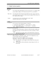
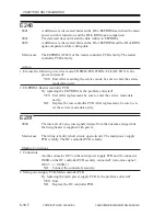
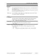
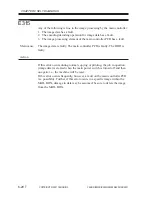
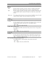
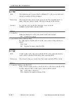
E220
0001
A fault is detected on the inverter PCB for the scanning lamp.
Main cause
The inverter PCB is faulty. The reader controller PCB is faulty.
Action
1. Wiring
Is the wiring from the scanning lamp to the reader controller PCB normal?
NO:
Connect the connector firmly, and correct or replace the wiring.
2. Inverter PCB, Reader controller PCB
Try replacing the lamp inverter PCB. Is the problem corrected?
YES: End.
NO:
Replace the reader controller PCB.
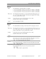
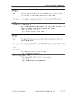
E225
0000
A specific level cannot be attained for the signal during CCD gain correc-
tion at power-on.
0002
The edge gain correction level is different from the correction level for the
preceding sheet by a specific level or more.
Main cause
The scanning lamp is faulty. The CCD PCB is faulty. The rear controller
PCB is faulty.
Action
1. Scanning lamp (LAMP1)
Is the lamp ON during the initial operation after the main power switch is
turned on?
NO:
Replace the scanning lamp.
2. CCD unit, Reader controller PCB
Try replacing the CCD unit. Is the problem corrected?
YES: End.
NO:
Replace the reader controller PCB.
Summary of Contents for iR2200 Series
Page 8: ......
Page 12: ......
Page 30: ......
Page 32: ......
Page 54: ......
Page 86: ......
Page 90: ......
Page 94: ......
Page 96: ......
Page 124: ......
Page 142: ......
Page 152: ......
Page 160: ......
Page 168: ......
Page 178: ......
Page 180: ......
Page 222: ......
Page 224: ......
Page 278: ......
Page 280: ......
Page 298: ......
Page 300: ......
Page 324: ......
Page 368: ......
Page 386: ......
Page 388: ......
Page 404: ......
Page 414: ......
Page 416: ......
Page 422: ......
Page 424: ......
Page 434: ......
Page 436: ......
Page 440: ......
Page 468: ......
Page 473: ......
Page 550: ......
Page 552: ......
Page 658: ......
Page 704: ......
Page 706: ......
Page 754: ......
Page 756: ......
Page 760: ......

