COPYRIGHT © 2001 CANON INC.
2000 2000 2000 2000
CANON iR2200/iR2800/iR3300 REV.0 MAR. 2001
CHAPTER 6 SELF DIAGNOSIS
6-27 T
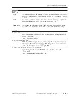
E712
0001
The communication is not resumed 3 sec or more after data has been writ-
ten to the error register of the communication IC (IPC) on the ADF control-
ler PCB.
0002
The transmission bit is not enabled 10 sec or more in the sync register of
the communication IC (IPC) on e reader controller PCB.
Main cause
The connect has poor connection. The main power supply PCB is faulty.
The ADF controller PCB is faulty. The reader controller PCB is faulty.
Action
1. Connector
Is the interface able between the ADF controller PCB and the reader con-
troller PCB normal?
NO:
Correct the cable.
2. Main power supply PCB
While the ADF is in operation, does the voltage between J203-2 (+) and
J203-1 (-) on the main power supply PCB change from 0 to about 24 V?
NO:
Replace the main power supply PCB.
3. ADF controller PCB, Reader controller PCB
Try replacing the ADF controller PCB. Is the problem corrected?
YES: End.
NO:
Replace the rear controller PCB.
Summary of Contents for iR2200 Series
Page 8: ......
Page 12: ......
Page 30: ......
Page 32: ......
Page 54: ......
Page 86: ......
Page 90: ......
Page 94: ......
Page 96: ......
Page 124: ......
Page 142: ......
Page 152: ......
Page 160: ......
Page 168: ......
Page 178: ......
Page 180: ......
Page 222: ......
Page 224: ......
Page 278: ......
Page 280: ......
Page 298: ......
Page 300: ......
Page 324: ......
Page 368: ......
Page 386: ......
Page 388: ......
Page 404: ......
Page 414: ......
Page 416: ......
Page 422: ......
Page 424: ......
Page 434: ......
Page 436: ......
Page 440: ......
Page 468: ......
Page 473: ......
Page 550: ......
Page 552: ......
Page 658: ......
Page 704: ......
Page 706: ......
Page 754: ......
Page 756: ......
Page 760: ......

