Chapter 1
1-21
1.2.4.2 Cleaning
0020-4274
The parts that should be cleaned by the customer to maintain the design performance and the cleaning method are described below.
The service engineer should instruct the customer to clean the machine at regular intervals (once a month).
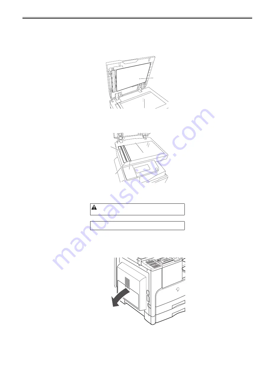
1. Pressure Plate
Clean the pressure plates [1] with a cloth dampened with water or neutral detergent and squeezed hard, and then wipe it with a dry soft cloth.
F-1-16
2. Document Glass/Vertical Size Plate
Clean the document glass [1] and vertical size plate [2] with a cloth dampened with water or neutral detergent and squeezed hard, and then wipe them with a dry
soft cloth.
When an ADF is installed, clean is document glass (small) [3] and glass holder [4] in the same manner.
F-1-17
3. Cleaning the Fixing Pressure Roller
If white streaks are seen on the printed paper, the fixing pressure roller can be dirty. If white streaks are seen on the printed paper, clean the fixing pressure roller
in the user mode. Be sure to clean the fixing pressure roller after replacing the toner bottle.
1) Press the Additional Functions key to enter the user mode.
2) Using the arrow keys, display the "Adjustment/Cleaning" menu.
3) Press the OK key.
4) Using the arrow keys, select "Fixing Unit Cleaning". Select "Yes" and then press the OK key.
5) Press the OK key. A cleaning pattern will be printed.
6) Open the manual feed tray.
F-1-18
When cleaning the fixing pressure roller, manually feed A4/LTR
paper.
MEMO:
The time required for cleaning is about 100 seconds.
[1]
[1]
[3]
[2]
[4]
Summary of Contents for iR2422 series
Page 1: ...May 12 2014 Service Manual iR2422 2420 2320 2318 Series...
Page 2: ......
Page 6: ......
Page 16: ...Contents...
Page 17: ...Chapter 1 Introduction...
Page 18: ......
Page 20: ......
Page 50: ......
Page 51: ...Chapter 2 Installation...
Page 52: ......
Page 54: ......
Page 58: ...Chapter 2 2 4 7 Left cover front 15 Right cover upper 8 Manual feed tray 16 Right cover lower...
Page 62: ...Chapter 2 2 8 8 Manual feed tray 16 Right cover lower...
Page 64: ...Chapter 2 2 10 8 Manual feed tray 16 Right cover lower...
Page 89: ...Chapter 2 2 35...
Page 90: ......
Page 91: ...Chapter 3 Main Controller...
Page 92: ......
Page 94: ......
Page 102: ......
Page 103: ...Chapter 4 Original Exposure System...
Page 104: ......
Page 135: ...9 Remove the reader heater left 1 Connector 2 1 pc Screw 3 1 pc F 4 73 2 3 1...
Page 136: ......
Page 137: ...Chapter 5 Laser Exposure...
Page 138: ......
Page 140: ......
Page 148: ...Chapter 5 5 8...
Page 149: ...Chapter 6 Image Formation...
Page 150: ......
Page 152: ......
Page 165: ...Chapter 7 Pickup Feeding System...
Page 166: ......
Page 192: ...Chapter 7 7 24...
Page 193: ...Chapter 8 Fixing System...
Page 194: ......
Page 196: ......
Page 207: ...Chapter 9 External and Controls...
Page 208: ......
Page 229: ...Chapter 10 Maintenance and Inspection...
Page 230: ......
Page 232: ......
Page 235: ...Chapter 11 Standards and Adjustments...
Page 236: ......
Page 238: ......
Page 240: ...Chapter 11 11 2...
Page 241: ...Chapter 12 Correcting Faulty Images...
Page 242: ......
Page 244: ......
Page 256: ......
Page 257: ...Chapter 13 Self Diagnosis...
Page 258: ......
Page 260: ......
Page 269: ...Chapter 14 Service Mode...
Page 270: ......
Page 272: ......
Page 287: ...Chapter 15 Upgrading...
Page 288: ......
Page 290: ......
Page 295: ...Chapter 16 Service Tools...
Page 296: ......
Page 298: ......
Page 300: ......
Page 301: ...Chapter 17 Backup Data...
Page 302: ......
Page 303: ...Contents Contents 17 1 Backup Data 17 1...
Page 304: ......
Page 306: ......
Page 307: ...May 12 2014...
Page 308: ......


