Chapter 6
6-6
6.5 Drum Unit
6.5.1 Outline of the Drum Unit
6.5.1.1 Outline
0020-4096
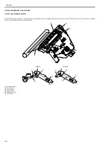
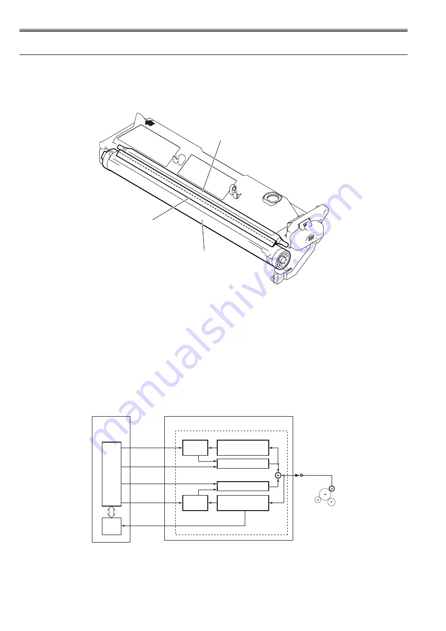
Major components of the drum unit are as follows:
F-6-7
[1] Photosensitive drum
[2] Cleaning blade
[3] Primary charging roller
6.5.2 Charging Mechanism
6.5.2.1 Primary Charging Bias Control
0020-4097
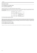
With the primary charging bias method, the drum is charged directly by the charging roller. In addition to a DC bias, an AC bias is applied to the primary charging
roller to stabilize charging. When the drum is charged, both AC and DC biases are applied. When the drum is discharged, only the AC bias is applied.
The ASIC on the DC controller PCB outputs the primary bias drive signal (/PRACFOT), primary AC bias ON/OFF signal (/PRACON), primary DC bias drive
signal (/PRDCFOT), and primary DC bias output level signal (/PRDCPWM) to apply the voltage generated by superimposing the primary AC bias over the primary
DC bias to the primary charging roller.
The primary AC bias is detected by the primary AC bias current detection circuit, and is fed back to the AC generator circuit via the comparison circuit.
The primary DC bias is detected by the primary DC bias current detection circuit, and is fed back to the DC generator circuit via the comparison circuit. Thus, this
machine controls the primary DC bias voltage. The primary DC bias voltage changes with the developing DC bias voltage according to the image density informa-
tion sent from the image processor PCB.
F-6-8
[3]
[1]
[2]
JP3/JP4
/PRACON
/PRACFOT
/PRDCPWM
/PRDCFOT
To primary
charging roller
Primary bias circuit
ASIC
CPU
Primary DC bias voltage
detection circuit
DC generation circuit
AC generation circuit
Compariso
circuit
Primary AC bias current
detection circuit
Comparison
circuit
Superimposition
High-voltage power supply PCB
DC controller PCB
J214
J100
/PRACMONI
Summary of Contents for iR2422 series
Page 1: ...May 12 2014 Service Manual iR2422 2420 2320 2318 Series...
Page 2: ......
Page 6: ......
Page 16: ...Contents...
Page 17: ...Chapter 1 Introduction...
Page 18: ......
Page 20: ......
Page 50: ......
Page 51: ...Chapter 2 Installation...
Page 52: ......
Page 54: ......
Page 58: ...Chapter 2 2 4 7 Left cover front 15 Right cover upper 8 Manual feed tray 16 Right cover lower...
Page 62: ...Chapter 2 2 8 8 Manual feed tray 16 Right cover lower...
Page 64: ...Chapter 2 2 10 8 Manual feed tray 16 Right cover lower...
Page 89: ...Chapter 2 2 35...
Page 90: ......
Page 91: ...Chapter 3 Main Controller...
Page 92: ......
Page 94: ......
Page 102: ......
Page 103: ...Chapter 4 Original Exposure System...
Page 104: ......
Page 135: ...9 Remove the reader heater left 1 Connector 2 1 pc Screw 3 1 pc F 4 73 2 3 1...
Page 136: ......
Page 137: ...Chapter 5 Laser Exposure...
Page 138: ......
Page 140: ......
Page 148: ...Chapter 5 5 8...
Page 149: ...Chapter 6 Image Formation...
Page 150: ......
Page 152: ......
Page 165: ...Chapter 7 Pickup Feeding System...
Page 166: ......
Page 192: ...Chapter 7 7 24...
Page 193: ...Chapter 8 Fixing System...
Page 194: ......
Page 196: ......
Page 207: ...Chapter 9 External and Controls...
Page 208: ......
Page 229: ...Chapter 10 Maintenance and Inspection...
Page 230: ......
Page 232: ......
Page 235: ...Chapter 11 Standards and Adjustments...
Page 236: ......
Page 238: ......
Page 240: ...Chapter 11 11 2...
Page 241: ...Chapter 12 Correcting Faulty Images...
Page 242: ......
Page 244: ......
Page 256: ......
Page 257: ...Chapter 13 Self Diagnosis...
Page 258: ......
Page 260: ......
Page 269: ...Chapter 14 Service Mode...
Page 270: ......
Page 272: ......
Page 287: ...Chapter 15 Upgrading...
Page 288: ......
Page 290: ......
Page 295: ...Chapter 16 Service Tools...
Page 296: ......
Page 298: ......
Page 300: ......
Page 301: ...Chapter 17 Backup Data...
Page 302: ......
Page 303: ...Contents Contents 17 1 Backup Data 17 1...
Page 304: ......
Page 306: ......
Page 307: ...May 12 2014...
Page 308: ......

