Contents
Contents
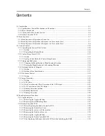
5.1 Construction ....................................................................................................................................................... 5-1
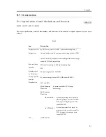
5.1.1 Specifications, Control Mechanisms, and Functions .................................................................................. 5-1
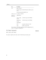
5.1.2 Major Components ...................................................................................................................................... 5-2
5.1.3 Construction of the Control System ............................................................................................................ 5-4
5.1.4 Reader Controller PCB................................................................................................................................ 5-5
5.2 Basic Sequence................................................................................................................................................... 5-7
5.2.1 Basic Sequence of Operation at Power-On ................................................................................................. 5-7
5.2.2 Basic Sequence of Operation in Response to a Press on the Start ............................................................. 5-7
5.2.3 Basic Sequence of Operation in Response to a Press on the Start ............................................................. 5-8
5.3 Various Control ................................................................................................................................................ 5-10
5.3.1 Controlling the Scanner Drive System ...................................................................................................... 5-10
5.3.1.1 Outline ................................................................................................................................................ 5-10
5.3.1.2 Controlling the Reader Motor ............................................................................................................ 5-10
5.3.2 Contact Image Sensor (CIS)...................................................................................................................... 5-12
5.3.2.1 Outline ................................................................................................................................................ 5-12
5.3.2.2 Analog Control Inside the Contact Image Sensor .............................................................................. 5-13
5.3.3 Enlargement/Reduction ............................................................................................................................. 5-14
5.3.3.1 Changing the Magnification in Main Scanning Direction ................................................................. 5-14
5.3.3.2 Varying the Magnification in Sub Scanning Direction ...................................................................... 5-14
5.3.4 Detecting the Size of Originals ................................................................................................................. 5-16
5.3.4.1 Outline ................................................................................................................................................ 5-16
5.3.4.2 Outline of Size Identification ............................................................................................................. 5-17
5.3.5 Dirt Sensor Control ................................................................................................................................... 5-19
5.3.5.1 Outline ................................................................................................................................................ 5-19
5.3.6 Image Processing....................................................................................................................................... 5-22
5.3.6.1 Outline ................................................................................................................................................ 5-22
5.3.6.2 CCD Drive.......................................................................................................................................... 5-23
5.3.6.3 Gain Correction and Offset Correction of the CCD Output............................................................... 5-23
5.3.6.4 A/D Conversion of the CCD Output .................................................................................................. 5-24
5.3.6.5 Shading Correction (outline) .............................................................................................................. 5-24
5.3.6.6 Shading Adjustment ........................................................................................................................... 5-24
5.3.6.7 Shading Correction............................................................................................................................. 5-24
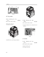
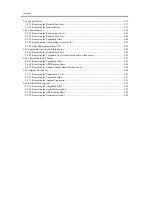
5.4 Parts Replacement Procedure........................................................................................................................... 5-26
5.4.1 Copyboard glass ........................................................................................................................................ 5-26
5.4.1.1 Removing the Copyboard Glass......................................................................................................... 5-26
5.4.1.2 Removing the ADF Reading Glass .................................................................................................... 5-27
5.4.2 Reader Controller PCB.............................................................................................................................. 5-28
5.4.2.1 Before Replacing the Reader Controller PCB.................................................................................... 5-28
5.4.2.2 Removing the Reader Rear Cover...................................................................................................... 5-28
5.4.2.3 Removing the rear cover of the machine............................................................................................ 5-29
5.4.2.4 Removing the flexible cable cover ..................................................................................................... 5-29
5.4.2.5 Removing the Copyboard Glass......................................................................................................... 5-30
5.4.2.6 Removing the Reader Controller PCB ............................................................................................... 5-31
5.4.2.7 After Replacing the Reader Controller PCB or After Initializing the RAM...................................... 5-35
Summary of Contents for iR4570 Series
Page 2: ...Download Free Service Manual And Resetter Printer at http printer1 blogspot com ...
Page 6: ...Download Free Service Manual And Resetter Printer at http printer1 blogspot com ...
Page 28: ...Download Free Service Manual And Resetter Printer at http printer1 blogspot com ...
Page 81: ...Chapter 2 Installation ...
Page 82: ......
Page 84: ......
Page 106: ...system setup network Ethernet driver setup auto detect ...
Page 126: ...F 2 94 3 2 3 1 ...
Page 127: ...Chapter 3 Basic Operation ...
Page 128: ......
Page 130: ......
Page 136: ......
Page 137: ...Chapter 4 Main Controller ...
Page 138: ......
Page 140: ......
Page 164: ......
Page 165: ...Chapter 5 Original Exposure System ...
Page 166: ......
Page 213: ...Chapter 6 Laser Exposure ...
Page 214: ......
Page 216: ......
Page 230: ......
Page 231: ...Chapter 7 Image Formation ...
Page 232: ......
Page 236: ......
Page 249: ...F 7 13 1 2 3 4 ...
Page 308: ......
Page 309: ...Chapter 8 Pickup Feeding System ...
Page 310: ......
Page 316: ......
Page 464: ......
Page 465: ...Chapter 9 Fixing System ...
Page 466: ......
Page 501: ...Chapter 10 External and Controls ...
Page 502: ......
Page 506: ......
Page 564: ......
Page 565: ...Chapter 11 MEAP ...
Page 566: ......
Page 568: ......
Page 573: ...Chapter 12 Maintenance and Inspection ...
Page 574: ......
Page 576: ......
Page 612: ......
Page 613: ...Chapter 13 Standards and Adjustments ...
Page 614: ......
Page 616: ......
Page 635: ...Chapter 14 Correcting Faulty Images ...
Page 636: ......
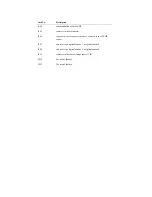
Page 675: ...T 14 22 Notation Description VR201 for factory use ...
Page 676: ......
Page 677: ...Chapter 15 Self Diagnosis ...
Page 678: ......
Page 680: ......
Page 757: ...Chapter 16 Service Mode ...
Page 758: ......
Page 760: ...Contents 16 8 1 COPIER 16 102 16 8 1 1 Copier List 16 102 ...
Page 869: ...Chapter 17 Service Tools ...
Page 870: ......
Page 871: ...Contents Contents 17 1 Special Tools 17 1 17 2 Oils and Solvents 17 2 ...
Page 872: ......
Page 875: ...Oct 8 2004 ...
Page 876: ......


