CHAPTER 3 ARRANGEMENT AND FUNCTIONS OF ELECTRICAL PARTS
3-16
1.8 Variable Resistors (VR), Light-Emitting Diodes (LED), and
Check Pins by PCB
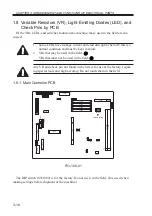
Of the VRs, LEDs, and switches found on the machine, those used in the field are dis-
cussed:
1.
Some LEDs have leakage current and emit dim light when off; this is a
normal condition and must be kept in mind:
2.
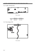
VRs that may be used in the field:
VRs that must not be used in the field:
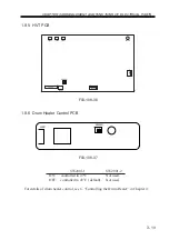
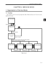
Any VR and check pin not found in the lists is for use at the factory, requir-
ing special tools and high accuracy. Do not touch them in the field.
1.8.1 Main Controller PCB
F03-108-01
The DIP switch (SW1002) is for the factory. Do not use it in the field. (It is used when
making settings before shipment of the machine.)
J1012
J1018
J1044
J1017
B1
B1
A1
6
40
1
1
B15
B18
A18
A15
A1
A22
B1
B22
A1
J1024
J1022
J1060
J1061
J1014
J1002
J1011
J1023
1
1
10
4
B40
B1
A40
A1
J1015
B1
B40
B40
A1
B1
A1
1
1
1 4
1
12
1
15
72
9
A40
A40
1
5
1
7
1
2
11
10
J1005
J1006
J1010
1
72
J1009
1
72
J1008
1
85
1
1
2
3
4
84
167
85
1
84
167
67
1
132
66
72
J1007
J1020
J1003
J1004
J1056
J1007
J1038
J1037
J1028
J1030
J1029
J1031
J1057
LED1001
J1013
LED1002
OFF
SW1002
Factory setting
Summary of Contents for IR5000 - iR B/W Laser
Page 72: ...CHAPTER 2 STANDARDS AND ADJUSTMENTS 2 52 Blank Page ...
Page 104: ......
Page 224: ......
Page 234: ......


