1-11
CHAPTER 1 IMAGE ADJUSTMENT BASIC PROCEDURE
5. Image Adjustment Basic Procedure
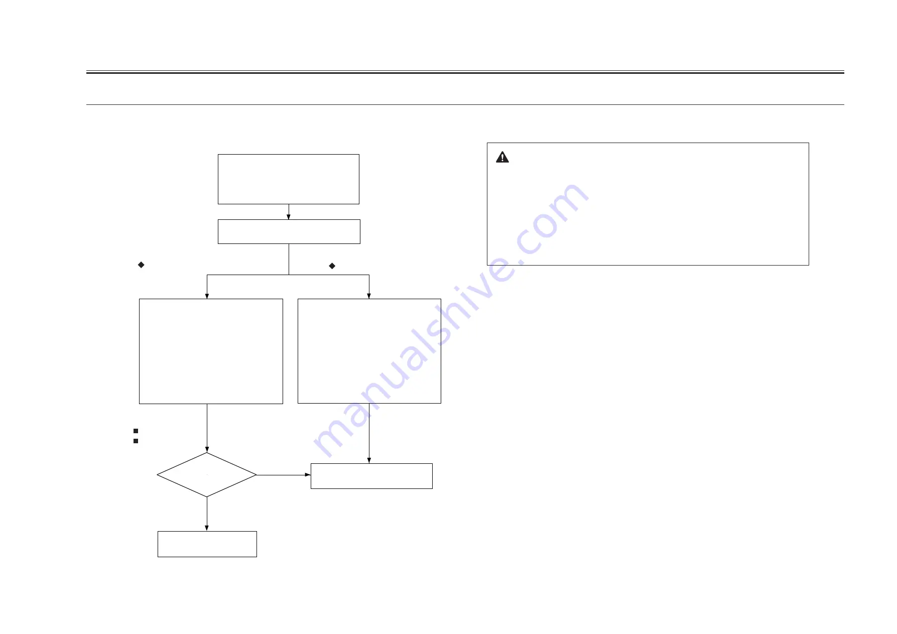
5.1 Making Pre-Checks
Using the NA3 Chart, make two copies each
in the following modes:
1. AE mode
2. Text mode
3. Text/photo mode
Generate several of the following test sheets:
1. 04 (blank)
2. 05 (halftone)
3. 06 (solid black)
Generate several each of the following
printer (PDL) images
1. Image with large background
(to check for fogging)
2. Image including solid black
(to check solid black density)
3. Image including halftone
(to check halftone density)
Check the following:
1. Height of charging wire
<Pre-Checks>
Clean the following:
1. Primary charging assembly grid wire
2. Primary charging wire
3. Pre-transfer charging wire
4. Transfer charging wire
If a fault is found on printer images,
If a fault is found on copy images,
Output Conditions
F value=5
potential control: ON
Perform 5.2 “ Making Checks on the
Printer Unit.”
Perform 5.4 “ Making Checks
on the Reader Unit.”
YES
NO
Are the test
prints normal?
Points to Note When Making Checks on the Printer Side
The machine's potential control mechanism is designed for both
copier image output and printer (PDL) image output, and its parameters
for potential control in service mode may be adjusted independently of
each other.
As such, when an image fault occurs, try to find out which side is
causing it, and generate the appropriate images (data) for adjustment of
related parameters.
Summary of Contents for IR5000 - iR B/W Laser
Page 72: ...CHAPTER 2 STANDARDS AND ADJUSTMENTS 2 52 Blank Page ...
Page 104: ......
Page 224: ......
Page 234: ......


