CHAPTER 2 STANDARDS AND ADJUSTMENTS
2-44
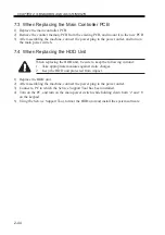
7.3 When Replacing the Main Controller PCB
1) Replace the main controller PCB.
2) Remove the counter memory PCB from the existing PCB, and mount it to the new PCB.
3) After assembling the machine, connect the power plug to the power outlet, and turn on
the main power switch.
7.4 When Replacing the HDD Unit
When replacing the HDD unit, be sure to keep the following in mind:
1.
Take appropriate measures against static charges.
2.
Keep the HDD unit protected from impact.
1) Replace the HDD unit.
2) After assembling the machine, connect the power plug to the power outlet.
3) Connect a PC to which the Service Support Tool has been installed.
4) Turn on the PC, and turn on the main power switch while holding down both ‘2’ and ‘8’
on the keypad.
5) Using the Service Support Tool, format the HDD unit and install the system software.
Summary of Contents for IR5000 - iR B/W Laser
Page 72: ...CHAPTER 2 STANDARDS AND ADJUSTMENTS 2 52 Blank Page ...
Page 104: ......
Page 224: ......
Page 234: ......

