CHAPTER 2 STANDARDS AND ADJUSTMENTS
2-51
Be sure to fit the clip [3] fully away from the sensor window, not letting it
coming into contact with the cover of the sensor.
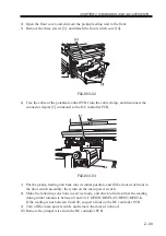
7) Insert the door switch tool into the door switch assembly.
8) Turn on the main power switch.
Be sure not to touch the potential senor assembly after turning on the power
switch.
9) Make the following selections in service mode, and check to make user that the reading
during initial rotation is between 0 and 30: COPIER>DISPLAY>DPOT>DPOT-K.
REF.
1.
If the reading is as indicated for method 1 but is not so for method 2,
suspect dirt on the or and a fault in the potential measurement unit.
2.
If the reading is as indicated for both method 1 and method 2, the sig-
nal paths and the operations from the potential sensor unit to the micro-
processor on the DC controller PCB may be assumed to be normal.
10) Turn off the main power switch.
11) Detach the electrode designed for checking potential sensors.
12) Mount the potential sensor support plate.
13) Turn on the main power switch.
14) Enable potential control.
Summary of Contents for IR5000 - iR B/W Laser
Page 72: ...CHAPTER 2 STANDARDS AND ADJUSTMENTS 2 52 Blank Page ...
Page 104: ......
Page 224: ......
Page 234: ......

