2-54
CHAPTER 2 STANDARDS AND ADJUSTMENTS
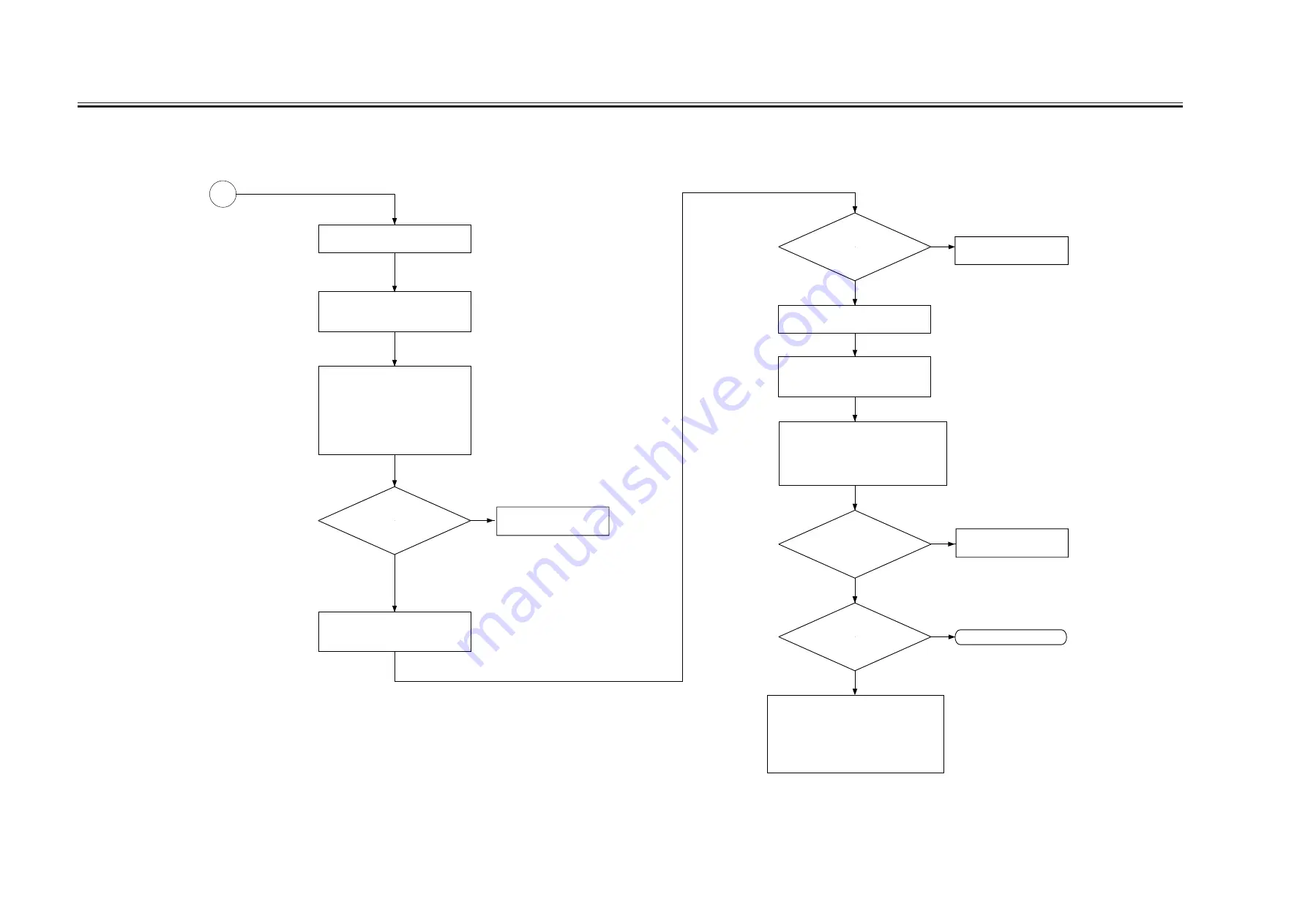
Measure the voltage DEV-DC-CNT
during printing of J102A-8 on the DC
controller PCB.
Check the developing assembly for
leakage; if normal, go to a check on the
transfer output.
Make the following selections (DC
value of the developing bias):
COPIER>DISPLAY>HV-STS>BIAS.
Covert the indication during printing
(V) into a control voltage with
reference to 8.5 "Potential Control
Conversion Table."
Is the
deferense between
the actual measurement of
DEV-DC-CNT and 'BIAS' in
service mode
± 10%?
YES
A
NO
Checking the Developing Bias Output
Disable potential control: COPIER>
OPTION>BODY>PO-CNT=0.
Measure the voltage TR-CNT during
printing of J102A-12 on the DC
controller PCB.
1) Check the transfer charging assembly for
leakage.
2) Make the following selections in service
mode, and try changing the setting:
COPIER>OPTION>BODY>FUZZY.
3) Try replacing paper.
Make the following selections in service
mode (level of current of transfer
charging). Convert the reading (
mA) during
printing into a control voltage based on 8.5
"Potential Control Conversion Table."
Replace the photosensitive
drum.
NO
YES
NO
YES
NO
Is the
difference between the
actual measurement of TR-CNT
and 'TR' in service
mode ± 10%?
Checking the Transfer Output
Is the toner
image on the photosensitive
drum before transfer
normal?
Replace the
high-voltage transformer.
Is the problem
corrected?
YES
Replace the DC controller
PCB.
Replace the DC controller
PCB.
END
Enable potential control: COPIER>
OPTION>BODY>PO-CNT=1
Summary of Contents for IR5000 - iR B/W Laser
Page 72: ...CHAPTER 2 STANDARDS AND ADJUSTMENTS 2 52 Blank Page ...
Page 104: ......
Page 224: ......
Page 234: ......

