COPYRIGHT © 2001 CANON INC.
2000 2000 2000 2000
CANON iR5000i/iR6000i REV.0 JUNE 2001
CHAPTER 5 PICK-UP/FEEDING SYSTEM
5-37 P
Zone
Pickup
Vertical path
Reversal/
duplexing
Other
T05-501-01
F05-501-01
Motor name
Right deck pickup motor
Left deck pickup motor
Cassette 3/4 pickup motor
Vertical path upper motor
Vertical path lower motor
Vertical path duplexing feed
motor
Reversal motor
Duplexing feed left motor
Duplexing feed right motor
Duplexing horizontal regis-
tration motor
Pre-registration motor
Delivery motor
Notation
(M11)
(M24)
(M12)
(M26)
(M27)
(M25)
(M14)
(M29)
(M18)
(M16)
(M17)
(M13)
Unit
See F05-201-01
See F05-201-01
See F05-201-02
See F05-201-02
See F05-201-02
See F05-401-02
See F05-401-01
See F05-401-02
See F05-401-02
See F05-404-01
See F05-201-01
-
Error detection
Motor error
Jam
Same as above.
Same as above.
Same as above.
Same as above.
Same as above.
Same as above.
Same as above.
Same as above.
Error code indi-
cation 'E051'
Motor error
Jam
Same as above.
Motor driver
M12
A7
A8
J104
4
5
6
3
2
1
J2104
DC controller
PCB
CPU
(IC5025)
A
A*
B
B*
+24V
+24V
A9
A10
A14
A10
A13
J2101
A12
A9
A11
+24V
5. Controlling the Pickup Assembly
5.1 Pickup Assembly Motors
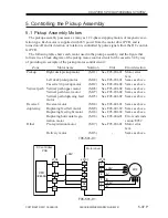
The pickup assembly possesses as many as 12 2-phase stepping motors of magnetic exci-
tation type. Each motor is supplied with 24V power from the motor driver PCB, and is
turned on/off and its direction of rotation is controlled by pulse signals from the DC control-
ler PCB.
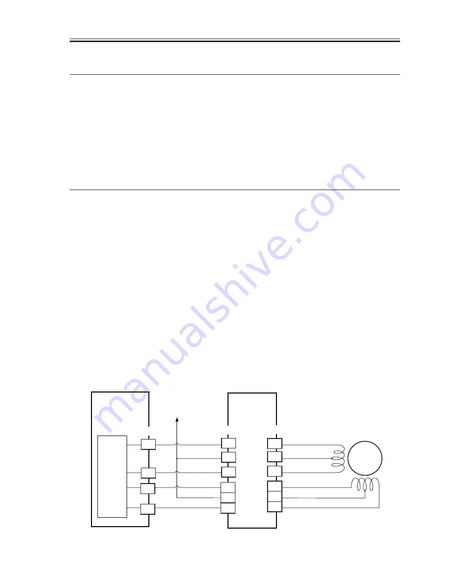
The following table shows each motor used in the pickup assembly, and the figure that
follows it is a block diagram of the pickup motor control circuit for the cassette 3/4 by way
of providing an example of the pickup motor control circuit:

