COPYRIGHT © 2001 CANON INC.
2000 2000 2000 2000
CANON iR5000i/iR6000i REV.0 JUNE 2001
CHAPTER 1 GENERAL DESCRIPTION
1-27 S
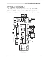
5.2 Outline of Electrical Circuitry
5.2.1 Construction of Electrical Circuitry
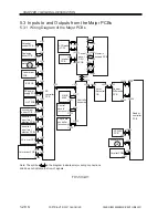
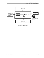
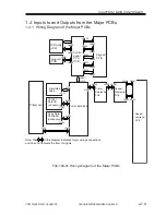
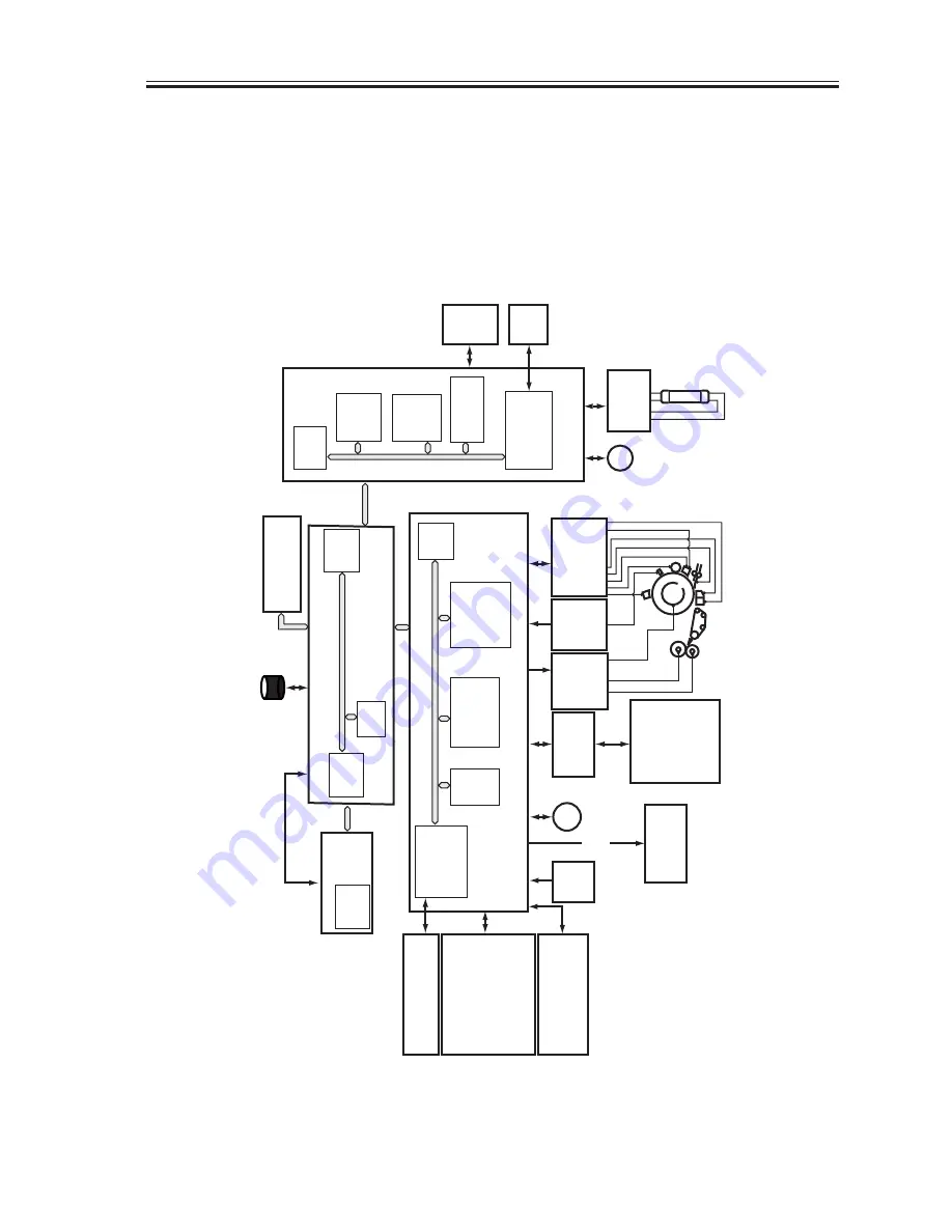
The machine’s major electrical mechanisms are controlled by the following PCBs:
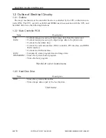
[1] Main controller PCB. Controls the system as a whole, performs image processing.
[2] DC controller PCB. Controls the printer unit, controls finisher communications.
[3] Reader controller PCB. Controls the reader controller, controls ADF communications.
F01-502-01
DC controller PCB
HVT PCB
P
otential
control
PCB
CCD/
AP
PCB
BD
PCB
ADF
Scanner
motor
Reader controller
PCB
Main controller PCB
Control
panel
In
v
e
rter
PCB
LA2
Laser scanner
motor
M15
M3
IC125
(CPU)
IC1010
(CPU)
IC121
IC122
(RAM)
(RAM)
DC load
• clutch
• solenoid
• motor
• sensor
• f
a
n
• etc.
Cassette inside
paper le
v
el detection
PCB
Duple
dr
iv
er PCB
DC load
• clutch
• solenoid
• motor
• sensor
• etc.
IC120
(IPC comm-
unication 2)
IC5021
(IPC com-
m
unication 2)
DIMM/R
O
M
(IC117)
IC5016
(R
OM)
• Finisher
(accessor
y)
(HDD)
IC6501
(CPU)
(DIMM-
R
OM)
IC5025
(CPU)
IC5008
IC5009
(RAM)
IC5027
(EEPR
OM)
IC104,105
IC109,110
IC127,130
(EEPR
OM)
Hard disk dr
iv
e
Accessor
y
boards
A
C
dr
iv
er
PCB
Laser dr
iv
er
PCB

