COPYRIGHT © 2001 CANON INC.
2000 2000 2000 2000
CANON iR5000i/iR6000i REV.0 JUNE 2001
CHAPTER 7 EXTERNALS AND CONTROLS
7-45 P
[15]
[15]
[16]
[17]
[18]
[17]
[1]
[2]
[3]
[4]
[5]
[6]
[7]
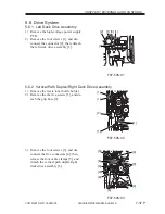
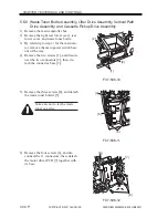
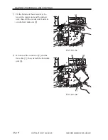
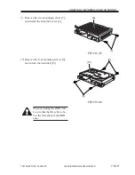
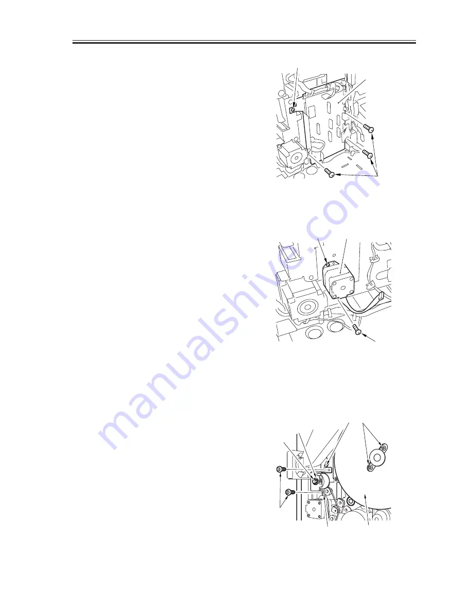
9) Remove the four screws [15], and dis-
connect the 11 connectors; then, detach
the motor driver PCB [16] together with
its base.
F07-507-07
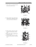
10) Remove the two screws [17], and detach
the cassette pickup motor [18].
F07-507-08
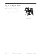
5.7.4 Pre-Registration Motor (M17) and Drum Motor (M1)
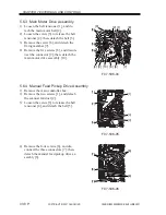
1) Remove the reader rear cover, rear up-
per cover, and right rear upper cover.
2) Remove the main controller box.
3) Remove the E-ring [1] and bushing [2].
4) Disconnect the connector [3], and re-
move the two screws [4]; then, detach
the pre-registration motor (M17) [5].
5) Remove the two screws [6], and detach
the flywheel [7].
F07-507-09

