COPYRIGHT © 2001 CANON INC.
2000 2000 2000 2000
CANON iR5000i/iR6000i REV.0 JUNE 2001
CHAPTER 4 TROUBLESHOOTING IMAGE FAULTS/MALFUNCTIONS
4-20 T
4. Troubleshooting Malfunctions
4.1 Troubleshooting by Malfunction
4.1.1 E000
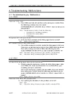
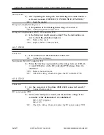
Thermistor (TH1, TH2)
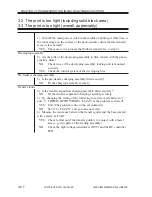
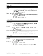
1) Clear E000, and turn off and then on the main power switch. Make
the following selections in service mode:
COPIER>DISPLAY>ANALOG. Does <FIX-U> show an increase in
temperature?
YES: The thermistor is faulty. Check the following:
•
thermistor for mounting condition
•
thermistor for soiled surface
•
connection
Fixing heater (H1, H2; open circuit)
2) Is the electrical continuity of the fixing upper heater normal?
NO:
Replace the fixing heater.
DC controller PCB, AC driver PCB (faulty)
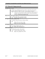
3) Turn off the main power switch, and let the fixing upper roller cool.
Then, turn on the main power switch. Clear E000, and trun off and
then on the main power switch. Make the following in service
mode: COPIER>I/O>DC-CON. Are bit 4 and bit 5 of IO-P12 ‘0’?
YES: Check the wiring; if normal, replace the DC controller PCB.
NO:
Check the wiring; if normal, replace the AC driver PCB.
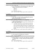
4.1.2 E001
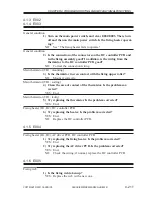
AC driver PCB (fixing heater drive circuit; short circuit)
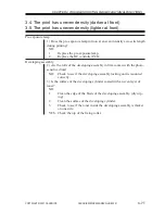
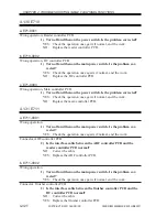
1) While keeping the main power switch off, let the fixing upper roller
cool. While at it, check each thermistor for a soiled surface, poor
mounting, and poor connection.
Turn on the main power switch, and clear E001; then, turn off and
then on the power switch. Make the following selections in service
mode: COPIER>DISPLAY>ANALOG. Is <FIX-U> about 230°C or
higher?
YES: Replace the AC driver PCB.
Thermistor (TH1, TH2), DC controller PCB
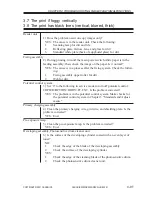
2) Try replacing the thermistor. Is the problem corrected?
YES: End.
NO:
Check the wiring; if normal, replace the DC controller PCB.

