COPYRIGHT © 2001 CANON INC.
2000 2000 2000 2000
CANON iR5000i/iR6000i REV.0 JUNE 2001
CHAPTER 4 TROUBLESHOOTING IMAGE FAULTS/MALFUNCTIONS
4-28 T
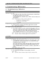
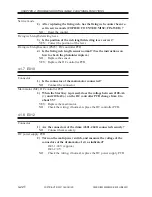
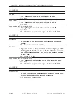
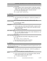
Scanner HP sensor (PS39), Reader controller PCB
2) Is the scanner HP sensor normal? (Check the instructions on how
to check photointerrupters.)
NO:
Replace the sensor.
YES: Check the wiring; if normal, replace the reader controller PCB.
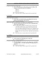
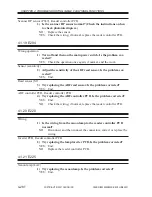
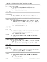
4.1.19 E204
Wrong operation
1) Turn off and then on the main power switch. Is the problem cor-
rected?
YES: Check the operation once again; if normal, end the work.
Sensor (sensitivity)
2) Adjust the sensitivity of the ADF read sensor. Is the problem cor-
rected?
YES: End.
Read sensor (S2)
3) Try replacing the ADF read sensor. Is the problem corrected?
YES: End.
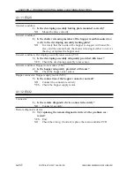
ADF controller PCB, Reader controller PCB
4) Try replacing the ADF controller PCB. Is the problem corrected?
YES: End.
NO:
Check the wiring; if normal, replace the reader controller PCB.
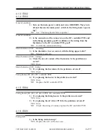
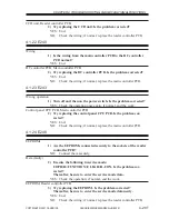
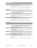
4.1.20 E220
Wiring
1) Is the wiring from the xenon lamp to the reader controller PCB
normal?
NO:
Disconnect and then connect the connectors; correct or replace the
wiring.
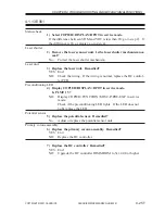
Inverter PCB, Reader controller PCB
2) Try replacing the lamp inverter PCB. Is the problem corrected?
YES: End.
NO:
Replace the reader controller PCB.
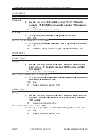
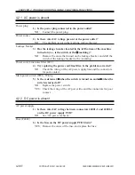
4.1.21 E225
Xenon lamp (LA2)
1) Try replacing the xenon lamp. Is the problem corrected?
YES: End.

