COPYRIGHT © 2001 CANON INC.
2000 2000 2000 2000
CANON iR5000i/iR6000i REV.0 JUNE 2001
CHAPTER 4 TROUBLESHOOTING IMAGE FAULTS/MALFUNCTIONS
4-39 T
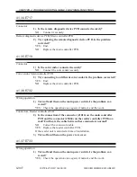
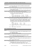
Wiring, DC load, DC power supply PCB
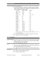
3) Turn off the main power switch. Is the voltage between the follow-
ing terminals on the DC power supply PCB as indicated when the
power is turned on in about 3 min?
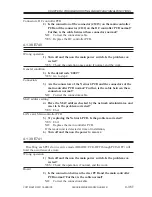
Connector
Output voltage
Remarks
J4014-1 to 5
3VA1
± 3%
J4017-1 to 5
3VA2
± 3%
J4003-7
3VA3
± 3%
J4015-1 to 3
3VB
+ 2%, - 2.5%
J4003-5
5V
± 3%
J4004-1
5V
± 3%
J4008-1
5V
± 3%
J4009-1
5V
± 3%
J4016-1, 2
5V
± 3%
J4003-3, 4
12VU
± 5%
J4005-1
24VU1
± 5%
J4004-3
24VU2
± 5%
J4009-3
24VU2
± 5%
J4003-1
24VU3
± 5%
J4006-1
24VU3
± 5%
J4007-1, 3
24VU4
± 5%
J4010-1
24VU4
± 5%
J4011-1
24VU4
± 5%
J4013-2
24VA
+ 7%, - 5%
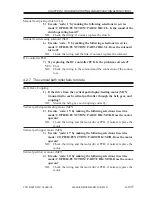
However, the above output voltages assume tolerances of ±10% in
the AC input power.
YES: Check the wiring from the DC power supply PCB to each load.
NO:
Replace the DC power supply PCB.
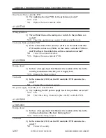
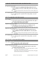
4.2.3 Pickup fails
General condition
1) Slide out and then in the cassette. Is the sound of the lifter falling
and the lifter motor rotating heard?
NO:
See “The lifter fails to move up.”
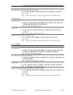
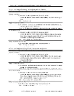
Sensor
2) In service mode (COPIER>DISPLAY>JAM), find out which sensor
has detected the jam. Is the sensor normal?
NO:
Check the wiring and the sensor lever; if normal, replace the sen-
sor.
Drive motor
3) Is each drive motor mounted correctly?
NO:
Mount the motor correctly.

