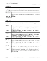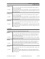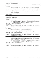
COPYRIGHT © 2001 CANON INC.
2000 2000 2000 2000
CANON iR5000i/iR6000i REV.0 JUNE 2001
CHAPTER 5 SERVICE MODE
5-39 T
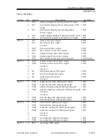
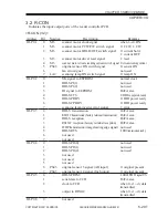
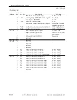
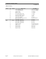
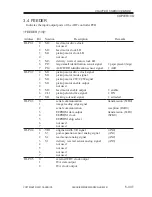
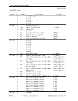
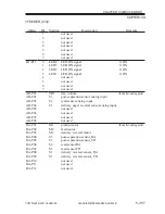
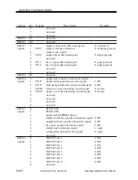
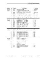
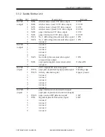
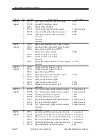
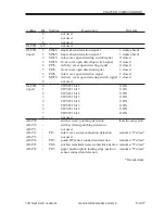
Address
IO-P017
(input)
IO-P018
(output)
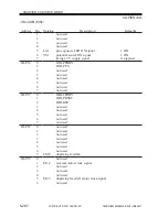
IO-P019
(output)
IO-P020
(output)
Bit
0
1
2
3
4
5
6
7
8
0
1
2
3
4
5
6
7
8
0
1
2
3
4
5
6
7
8
0
1
2
3
4
5
6
7
8
Notation
PI15
PI16
MS5
MS.
MS1
MS4
MS6
M7
M7
M1P
M1P
M2
M2
M6
M6
M2P
M9
M9
M8
M8
M1
M1
M4
M3
Description
joint detection signal
cover open/closed detection signal
saddle unit connection detection signal
tray upper limit detecting switch signal
tray safety switch signal
cover open/closed detecting switch signal
shutter closed detecting switch signal
swing guide closed detecting switch signal
not used
swing motor CW drive output
swing motor CCW drive output
punch motor CCW drive output
punch motor CW drive output
delivery motor CCW drive output
delivery motor CW drive output
stapler motor CCW drive output
stapler motor CW drive output
not used
stepping motor OFF
punch horizontal registration motor current switch
inlet feed motor current switch 2
inlet feed motor current swing 1
No. 2 feed motor current switch 2
No. 2 feed motor current switch 1
No. 1 feed motor current switch 2
No. 1 feed motor current switch 1
not used
punch unit EEPROM data out
punch unit EEPROM CS
punch unit EEPROM CLK
not used
not used
height sensor ON/OFF
stapler shift motor current switch
alignment motor current switch
not used
Remarks
1: connected
1: closed
1: upper limit
0: safe
0: closed
1: closed
0: closed
1: CW
1: CCW
0: CCW
0: CW
1: CCW
1: CW
0: CCW
0: CW
1: OFF
0: ON
0: ON
0: ON
0: ON
0: ON
0: ON
0: ON
0: ON
0: ON

