COPYRIGHT © 2001 CANON INC.
2000 2000 2000 2000
CANON iR5000i/iR6000i REV.0 JUNE 2001
CHAPTER 5 SERVICE MODE
5-43 T
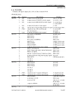
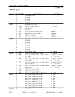
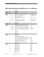
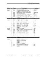
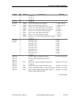
Address
IO-P032
IO-P033
(input)
IO-P034
(input)
AD-P09
AD-P10
AD-P11
AD-P12
AD-P13
AD-P14
AD-P15
AD-P16
Bit
6
7
8
0-8
0
1
2
3
4
5
6
7
8
0
1
2
3
4
5
6
7
8
-
-
-
-
-
-
-
-
Notation
MS4S
MS6S
MS1S
MS2S
PI3S
PI2S
PI9S
MS3S
PI9
PI13
PI16
PI15
Description
not used
not used
not used
not used
staple absent detection signal 2
staple absent detection signal 1
inlet cover open detecting switch signal
front cover open detecting switch signal
delivery cover open detecting signal
front cover open detection signal
inlet cover open detection signal
delivery cover open detecting switch signal
not used
TIP SW1 bit 8
TIP SW1 bit 7
TIP SW1 bit 6
TIP SW1 bit 5
TIP SW1 bit 4
TIP SW1 bit 3
TIP SW1 bit 2
TIP SW1 bit 1
not used
stitcher (rear) punching detection
stitcher (front) punching detection
not used
inlet cover sensor connection detection
not used
guide HP sensor connection detection
stitcher compartment sensor connection detection
paper push-on plate leading edge position
sensor connection detection
Remarks
1: staple absent
1: staple absent
0: closed
0: closed
0: closed
1: closed
1: closed
1: closed
0: ON
0: ON
0: ON
0: ON
0: ON
0: ON
0: ON
0: ON
(hereafter, analog ports)
connected at ‘7F’ or lower*
connected at ‘7F’ or lower*
connected at ‘7F’ or lower*
connected at ‘7F’ or lower*
*Hexadecimal.

