COPYRIGHT © 2001 CANON INC.
2000 2000 2000 2000
CANON iR5000i/iR6000i REV.0 JUNE 2001
CHAPTER 6 SELF DIAGNOSIS
6-14 T
1.3 Self Diagnosis of the Finisher
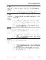
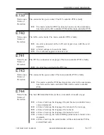
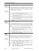
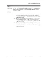
E500
Main Cause
The finisher controller PCB is faulty. The DC controller PCB is faulty.
Mode of
Detection
0001 The communication between the host machine and the finisher has
been interrupted; this error is detected by the host machine.
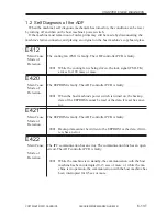
E503
Main Cause
The saddle stitcher controller PCB is faulty. The finisher controller PCB is
faulty.
Mode of
Detection
0002 The communication between the saddle stitcher controller PCB
and the finisher controller PCB has been interrupted.
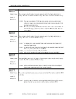
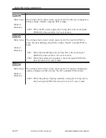
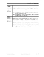
E504
Main Cause
The height sensor (PS1) is faulty. The finisher controller PCB is faulty.
Mode of
Detection
0001 Communication between the height sensor and the finisher control-
ler PCB is not possible, or communication data has an error.
0002 Communication between the height sensor and the finisher control-
ler PCB is not possible for a specific period of time.
0003 At time of power-on, the connector of the height sensor is found to
be disconnected.
0004 When the height sensor is being adjusted using the DIP switch, an
error occurred during the adjustment.
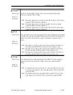
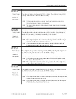
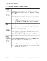
E505
Main Cause
The EEPROM is faulty. The finisher controller PCB is faulty. The puncher
driver PCB is faulty.
Mode of
Detection
0001 When the power switch is turned on, the check sum of the
EEPROM on the finisher controller PCB is found to have an error.
0002 When the power switch is turned on, the check sum of the
EEPROM on the puncher driver PCB is found to have an error.


