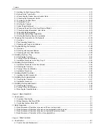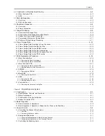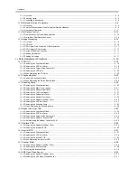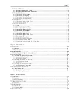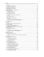
Contents
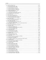
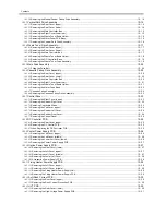
12.3.1
Scheduled Servicing Basic Procedure .................................................................................................................12- 4
12.3.2
Periodical Servicing Chart Reader Unit................................................................................................................12- 4
12.3.3
Periodical Servicing Chart Printer Unit.................................................................................................................12- 5
12.3.4
Points to Note for Periodical Servicing.................................................................................................................12- 6
12.4
Cleaning ................................................................................................................................................. 12- 7
12.4.1
Cleaning the Primary Anti-Stray Sheet ................................................................................................................12- 7
12.4.2
Cleaning the Developing Anti-Stray Sheet...........................................................................................................12- 7
12.4.3
Cleaning the Cleaner Side Scraper......................................................................................................................12- 7
12.4.4
Cleaning the Photosensitive Drum.......................................................................................................................12- 8
Chapter 13
Standards and Adjustments
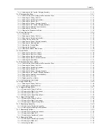
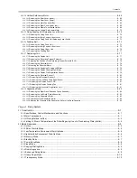
13.1
Image Adjustment Basic Procedure ....................................................................................................... 13- 1
13.1.1
Making Pre-Checks..............................................................................................................................................13- 1
13.1.2
Making Checks on the Printer Unit (1/2) ..............................................................................................................13- 1
13.1.3
Making Checks on the Printer Unit (2/2) ..............................................................................................................13- 3
13.1.4
Making Checks on the Reader Unit .....................................................................................................................13- 5
13.1.5
Checking the Potential System ............................................................................................................................13- 8
13.1.6
Checking the Surface Potential Control System ................................................................................................13- 11
13.1.7
Potential Control System Conversion Table ......................................................................................................13- 14
13.1.8
Emergency Measures for a Fault in the Potential Sensor..................................................................................13- 17
13.2
Image Adjustments............................................................................................................................... 13- 18
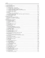
13.2.1
Standards of Image Position ..............................................................................................................................13- 18
13.2.2
Checking the Image Position .............................................................................................................................13- 18
13.2.3
Adjusting Side Registration ................................................................................................................................13- 18
13.2.4
Adjusting the Image Leading Edge Margin ........................................................................................................13- 19
13.2.5
Adjusting the Left/Right Non-Image Width .........................................................................................................13- 20
13.2.6
Adjusting the Leading Edge Non-Image Width ..................................................................................................13- 20
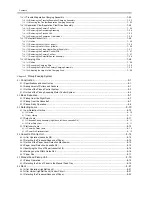
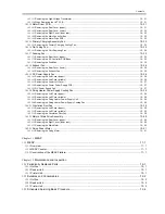
13.3
Scanning System.................................................................................................................................. 13- 21
13.3.1
After Replacing the Reader Controller PCB.......................................................................................................13- 21
13.3.2
When Replacing the CCD Unit...........................................................................................................................13- 21
13.3.3
Adjusting the Position of the No. 1/No. 2 Mirror Base........................................................................................13- 21
13.3.4
When Replacing the Platen Board Glass...........................................................................................................13- 22
13.3.5
When Replacing the Reading Glass ..................................................................................................................13- 22
13.3.6
When Replacing the Scanning Lamp.................................................................................................................13- 22
13.3.7
When Replacing the Inverter PCB .....................................................................................................................13- 22
13.4
Laser Exposure System ....................................................................................................................... 13- 23
13.4.1
When Replacing the Scanner Unit .....................................................................................................................13- 23
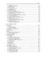
13.5
Image Formation System ..................................................................................................................... 13- 24
13.5.1
Outline of the Charging Wire..............................................................................................................................13- 24
13.5.2
Routing the Charging Wire.................................................................................................................................13- 24
13.5.3
Routing the Grid for the Primary Charging Assembly ........................................................................................13- 24
13.5.4
Adjusting the Height of the Charging Wire .........................................................................................................13- 25
13.5.5
Mounting the Cleaning Blade .............................................................................................................................13- 25
13.5.6
Mounting the Side Seal ......................................................................................................................................13- 26
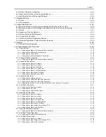
13.6
Fixing System ....................................................................................................................................... 13- 27
13.6.1
Applying Grease After Replacing the Fixing Roller ............................................................................................13- 27
13.6.2
Adjusting the Nip Width......................................................................................................................................13- 27
13.6.3
Adjusting the Position of the Fixing Web Solenoid (SL9)...................................................................................13- 27
13.6.4
After Replacing the Fixing Web..........................................................................................................................13- 27
13.6.5
Adjusting the Position of he Fixing Inlet Guide Solenoid (SL1)..........................................................................13- 27
13.6.6
Adjusting the Position of the Fixing Inlet Guide..................................................................................................13- 27
13.7
Electrical Components.......................................................................................................................... 13- 29
13.7.1
When Replacing the DC Controller PCB............................................................................................................13- 29
13.7.2
When Replacing the HVT PCB ..........................................................................................................................13- 29
Summary of Contents for iR5570 Series
Page 1: ...Mar 29 2005 Service Manual iR6570 5570 Series ...
Page 2: ......
Page 6: ......
Page 26: ...Contents ...
Page 27: ...Chapter 1 Introduction ...
Page 28: ......
Page 30: ......
Page 55: ...Chapter 2 Installation ...
Page 56: ......
Page 58: ...Contents 2 9 3 Mounting the Cassette Heater 2 34 ...
Page 98: ......
Page 99: ...Chapter 3 Basic Operation ...
Page 100: ......
Page 102: ......
Page 110: ......
Page 111: ...Chapter 4 Main Controller ...
Page 112: ......
Page 114: ......
Page 135: ...Chapter 5 Original Exposure System ...
Page 136: ......
Page 181: ...Chapter 6 Laser Exposure ...
Page 182: ......
Page 184: ......
Page 192: ......
Page 193: ...Chapter 7 Image Formation ...
Page 194: ......
Page 198: ......
Page 259: ...Chapter 8 Pickup Feeding System ...
Page 260: ......
Page 350: ......
Page 351: ...Chapter 9 Fixing System ...
Page 352: ......
Page 401: ...Chapter 10 External and Controls ...
Page 402: ......
Page 406: ......
Page 448: ......
Page 449: ...Chapter 11 MEAP ...
Page 450: ......
Page 452: ......
Page 455: ...Chapter 12 Maintenance and Inspection ...
Page 456: ......
Page 458: ......
Page 468: ......
Page 469: ...Chapter 13 Standards and Adjustments ...
Page 470: ......
Page 505: ...Chapter 14 Correcting Faulty Images ...
Page 506: ......
Page 508: ......
Page 537: ...Chapter 15 Self Diagnosis ...
Page 538: ......
Page 540: ......
Page 565: ...Chapter 16 Service Mode ...
Page 566: ......
Page 568: ......
Page 633: ...Chapter 17 Upgrading ...
Page 634: ......
Page 636: ......
Page 641: ...Chapter 17 17 5 F 17 4 HDD Boot ROM Flash ROM System Software ...
Page 646: ...Chapter 17 17 10 F 17 11 8 Click START F 17 12 ...
Page 675: ...Chapter 17 17 39 F 17 59 2 Select the data to download F 17 60 3 Click Start ...
Page 677: ...Chapter 18 Service Tools ...
Page 678: ......
Page 680: ......
Page 683: ...Mar 29 2005 ...
Page 684: ......

