Chapter 13
13-17
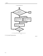
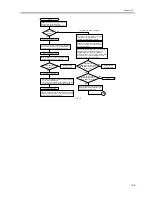
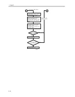
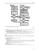
13.1.8 Emergency Measures for a Fault in the Potential Sensor
0008-7916
If the potential sensor goes out of order and, as a result, a transfer separation fault occurs, use the following service mode item to avoid problems; be sure,
however, that this is merely a tentative remedy to be used until the potential sensor is replaced:
1. COPIER>OPTION>TEMPO>F-POT-SW (Category 2)
Å@Set '1' if a transfer separation fault occurs when the potential sensor has gone out of order.
2. COPIER>OPTION>TEMPO>F-POT-D (Category 2)
Å@This is enabled when '1' is set for the foregoing service mode item.
0: if the user primarily uses originals with a low image ratio (text original). (default)
1: if the user primarily uses originals with a high image ratio (photo originals)
2: if re-transfer (drop-out about 50 mm of leading edge) occurs.
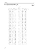
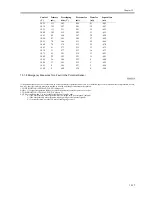
10.25
131
543
-299
41
-443
10.30
122
547
-301
38
-447
10.35
113
551
-303
35
-451
10.40
105
555
-305
33
-455
10.45
96
558
-307
30
-458
10.50
87
562
-309
27
-462
10.55
78
566
-311
24
-466
10.60
70
570
-313
22
-470
10.65
61
573
-315
19
-473
10.70
52
577
-317
16
-477
10.75
43
581
-319
13
-481
10.80
35
585
-321
11
-485
10.85
26
588
-323
8
-488
10.90
17
592
-325
5
-492
10.95
8
596
-327
2
-496
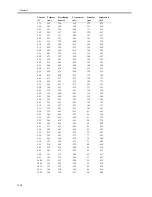
11.00
0
600
-330
0
-500
Control
(V)
Primary
(uA)
Developing
bias (V)
Pre-transfer
(uA)
Transfer
(uA)
Separation
(uA)
Summary of Contents for iR5570 Series
Page 1: ...Mar 29 2005 Service Manual iR6570 5570 Series ...
Page 2: ......
Page 6: ......
Page 26: ...Contents ...
Page 27: ...Chapter 1 Introduction ...
Page 28: ......
Page 30: ......
Page 55: ...Chapter 2 Installation ...
Page 56: ......
Page 58: ...Contents 2 9 3 Mounting the Cassette Heater 2 34 ...
Page 98: ......
Page 99: ...Chapter 3 Basic Operation ...
Page 100: ......
Page 102: ......
Page 110: ......
Page 111: ...Chapter 4 Main Controller ...
Page 112: ......
Page 114: ......
Page 135: ...Chapter 5 Original Exposure System ...
Page 136: ......
Page 181: ...Chapter 6 Laser Exposure ...
Page 182: ......
Page 184: ......
Page 192: ......
Page 193: ...Chapter 7 Image Formation ...
Page 194: ......
Page 198: ......
Page 259: ...Chapter 8 Pickup Feeding System ...
Page 260: ......
Page 350: ......
Page 351: ...Chapter 9 Fixing System ...
Page 352: ......
Page 401: ...Chapter 10 External and Controls ...
Page 402: ......
Page 406: ......
Page 448: ......
Page 449: ...Chapter 11 MEAP ...
Page 450: ......
Page 452: ......
Page 455: ...Chapter 12 Maintenance and Inspection ...
Page 456: ......
Page 458: ......
Page 468: ......
Page 469: ...Chapter 13 Standards and Adjustments ...
Page 470: ......
Page 505: ...Chapter 14 Correcting Faulty Images ...
Page 506: ......
Page 508: ......
Page 537: ...Chapter 15 Self Diagnosis ...
Page 538: ......
Page 540: ......
Page 565: ...Chapter 16 Service Mode ...
Page 566: ......
Page 568: ......
Page 633: ...Chapter 17 Upgrading ...
Page 634: ......
Page 636: ......
Page 641: ...Chapter 17 17 5 F 17 4 HDD Boot ROM Flash ROM System Software ...
Page 646: ...Chapter 17 17 10 F 17 11 8 Click START F 17 12 ...
Page 675: ...Chapter 17 17 39 F 17 59 2 Select the data to download F 17 60 3 Click Start ...
Page 677: ...Chapter 18 Service Tools ...
Page 678: ......
Page 680: ......
Page 683: ...Mar 29 2005 ...
Page 684: ......


