Chapter 13
13-21
13.3 Scanning System
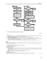
13.3.1 After Replacing the Reader Controller PCB
0008-7884
Be sure to generate the latest P-PRINT printout before replacing the
reader controller PCB
- If you are initializing the RAM on the reader controller without
replacing the PCB,
Using the SST, upload the backup data of R-CON; initialize the RAM,
and then download the data, thus eliminating the need for the
following.
1) Using the SST, download the latest system software (R-CON).
2) Make the following selections in service mode: COPIER>
FUNCTION> CLEAR> R-CON. Then, press the OK key to execute
RAM initialization. Thereafter, turn off and then back on the main
power.
3) Enter the appropriate settings for the following items in service mode:
a. settings indicated on the service label (found behind the reader unit
front cover)
a-1 image read start position adjustment (X direction; in fixed reading
mode) COPIER>ADJUST>ADJ-XY>ADJ-X
a-2 image read start position adjustment (Y direction; in fixed reading
mode) COPIER>ADJUST>ADJ-XY>ADJ-Y
a-3 shading position adjustment (in fixed reading mode)
COPIER>ADJUST>ADJ-XY>ADJ-S
a-4 feeder mode main scanning position adjustment
COPIER>ADJUST>ADJ-XY>ADJ-Y-DF
a-5 ADF stream reading CCD reading position
COPIER>ADJUST>ADJ-XY>STRD-POS
The machine retains ADF-related service data in the RAM of its reader
controller,
thus necessitating ADF adjustment whenever you have replaced the
reader controller or initialized the RAM.
b. original stop position adjustment
FEEDER>ADJSUT>DOCST
c. original feed speed (magnification) adjustment
FEEDER>ADUST>LA-SPEED
4) Make adjustments using the following service mode items:
a. ADF sensor sensitivity adjustment
FEEDER>FUNCTION>SENS-INT
b. tray width adjustment
FEEDER>FUNCTION>TRY-A4
FEEDER>FUNCTION>TRY-A5R
FEEDER>FUNCTION>TRY-LTR
FEEDER>FUNCTION>TRY-LTRR
c. white plate data adjustment
COPIER>FUNCTION>CCD>CCD-ADJ
d. ADF white level adjustment
COPIER>FUNCTION>CCD>DF-WLVL1
COPIER>FUNCTION>CCD>DF-WLVL2
Be sure to perform white plate data adjustment before performing ADF
white level adjustment.
After having made the foregoing adjustments, put the P-PRINT printout
in the service book case, replacing the previous P-PRINT printout.
13.3.2 When Replacing the CCD Unit
0009-1976
Execute the following in service mode:
1) white plate data adjustment (COPIER> FUNCTION> CCD> CCD-
ADJ)
2) ADF white level adjustment (COPIER> FUNCTION> CCD> DF-
WLVL1/2)
Be sure to perform white plate data adjustment before performing ADF
white level plate.
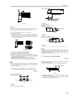
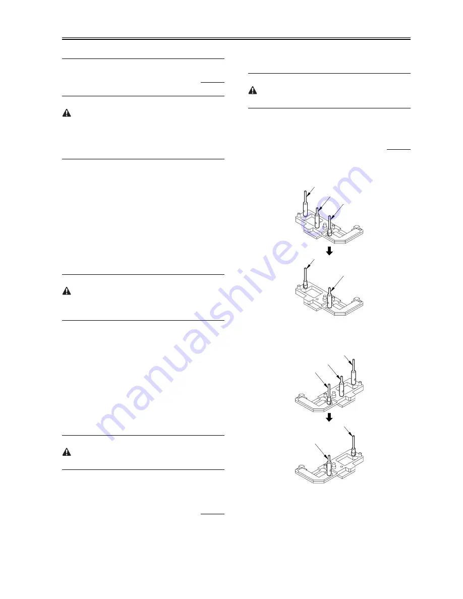
13.3.3 Adjusting the Position of the No. 1/No. 2
Mirror Base
0008-7883
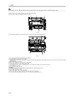
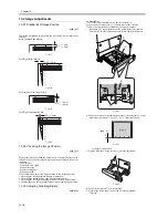
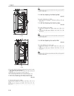
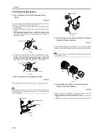
1) Arrange the mirror positioning tool (FY9-3009-040) so that it is ready
for use in the machine (by changing the pin position; REAR).
F-13-33
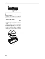
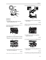
2) Arrange the mirror positioning tool so that it is ready for use in the
machine (by changing the pin position; FRONT).
F-13-34
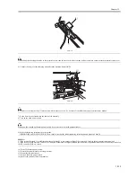
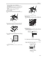
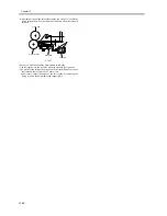
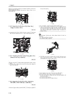
3) Fit the pins of the mirror positioning tool (front [2]; rear [3]) into the
appropriate holes of the No. 1/No. 2 mirror base).
[A]
[B]
[C]
[B]
[A]
[A]
[B]
[C]
[B]
[A]
Summary of Contents for iR5570 Series
Page 1: ...Mar 29 2005 Service Manual iR6570 5570 Series ...
Page 2: ......
Page 6: ......
Page 26: ...Contents ...
Page 27: ...Chapter 1 Introduction ...
Page 28: ......
Page 30: ......
Page 55: ...Chapter 2 Installation ...
Page 56: ......
Page 58: ...Contents 2 9 3 Mounting the Cassette Heater 2 34 ...
Page 98: ......
Page 99: ...Chapter 3 Basic Operation ...
Page 100: ......
Page 102: ......
Page 110: ......
Page 111: ...Chapter 4 Main Controller ...
Page 112: ......
Page 114: ......
Page 135: ...Chapter 5 Original Exposure System ...
Page 136: ......
Page 181: ...Chapter 6 Laser Exposure ...
Page 182: ......
Page 184: ......
Page 192: ......
Page 193: ...Chapter 7 Image Formation ...
Page 194: ......
Page 198: ......
Page 259: ...Chapter 8 Pickup Feeding System ...
Page 260: ......
Page 350: ......
Page 351: ...Chapter 9 Fixing System ...
Page 352: ......
Page 401: ...Chapter 10 External and Controls ...
Page 402: ......
Page 406: ......
Page 448: ......
Page 449: ...Chapter 11 MEAP ...
Page 450: ......
Page 452: ......
Page 455: ...Chapter 12 Maintenance and Inspection ...
Page 456: ......
Page 458: ......
Page 468: ......
Page 469: ...Chapter 13 Standards and Adjustments ...
Page 470: ......
Page 505: ...Chapter 14 Correcting Faulty Images ...
Page 506: ......
Page 508: ......
Page 537: ...Chapter 15 Self Diagnosis ...
Page 538: ......
Page 540: ......
Page 565: ...Chapter 16 Service Mode ...
Page 566: ......
Page 568: ......
Page 633: ...Chapter 17 Upgrading ...
Page 634: ......
Page 636: ......
Page 641: ...Chapter 17 17 5 F 17 4 HDD Boot ROM Flash ROM System Software ...
Page 646: ...Chapter 17 17 10 F 17 11 8 Click START F 17 12 ...
Page 675: ...Chapter 17 17 39 F 17 59 2 Select the data to download F 17 60 3 Click Start ...
Page 677: ...Chapter 18 Service Tools ...
Page 678: ......
Page 680: ......
Page 683: ...Mar 29 2005 ...
Page 684: ......

