Chapter 14
14-17
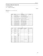
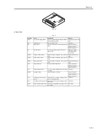
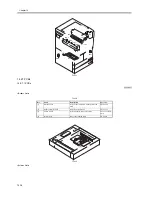
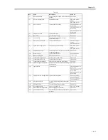
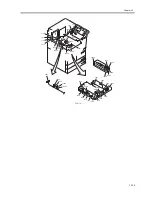
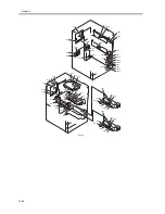
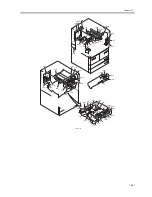
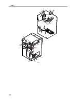
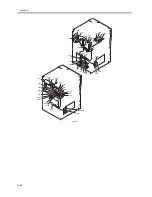
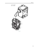
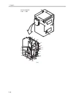
T-14-19
Ref.
Name
Description
Parts No.
[1]
DC controller PCB
controls the power supply to the printer unit/
finisher
FM2-3646
[2]
DC power supply PCB
supplies DC power
FK2-0799 (100V/
120V)
FK2-0800 (230V)
[3]
AC driver PCB
controls the AC circuitry
FM2-3044 (100V; AC
driver unit)
FM2-3043 (120V; AC
driver unit)
FM2-3045 (230V; AC
driver unit)
[4]
motor driver PCB
controls the motor
FM2-3655
[5]
HVT PCB
generates high voltage
FM2-3653
[6]
potential PCB
controls the surface potential of the
photosensitive drum
FM2-3040
[7]
drum heater control PCB
controls the drum heater
FM2-0841 (100V/
120V)
FM2-0842 (230V)
[8]
option power supply PCB
supplies power to the finisher
FK2-0797 (100V/
120V)
FK2-0798 (230V)
[9]
duplexing drive PCB
controls the sensors, motors, and solenoids
of the duplexing unit
FM2-3654
[10]
laser drive PCB
controls the laser drive
FM2-3670 (laser
scanner unit)
[11]
BD developing PCB
detects the laser beam
[12]
control panel keypad PCB
controls the keys and LEDs
FM2-1250
[13]
control panel CPU PCB
controls the control panel
FM2-1249
[14]
control panel inverter PCB
adjusts the contrast of the control panel
FM2-1251
[15]
rush-current prevention PCB
prevents rush current to the fixing feeding/
duplexing unit
FG6-4978
[16]
capacitor PCB
removes noise
FM2-3044 (100V; AC
driver unit)
FM2-3043 (120V; AC
driver unit)
FM2-3045 (230V; AC
driver unit)
[17]
fixing heater power supply PCB controls the fixing heater
FM2-3647 (100V)
FM2-3648 (120V)
FM2-3649 (230V)
[18]
main controller PCB
performs digital image processing/system
control
FM2-3794
[19]
differential PCB
converts communication signals
FM2-3796
[20]
PCI expansion PCB
serves as a relay PCB
FG3-1745 (option)
[21]
drum cleaner thermistor PCB
detects clogging of the cleaner
FM2-3661
[22]
potential sensor PCB
measures the photosensitive drum surface
potential
FM2-3040
Summary of Contents for iR5570 Series
Page 1: ...Mar 29 2005 Service Manual iR6570 5570 Series ...
Page 2: ......
Page 6: ......
Page 26: ...Contents ...
Page 27: ...Chapter 1 Introduction ...
Page 28: ......
Page 30: ......
Page 55: ...Chapter 2 Installation ...
Page 56: ......
Page 58: ...Contents 2 9 3 Mounting the Cassette Heater 2 34 ...
Page 98: ......
Page 99: ...Chapter 3 Basic Operation ...
Page 100: ......
Page 102: ......
Page 110: ......
Page 111: ...Chapter 4 Main Controller ...
Page 112: ......
Page 114: ......
Page 135: ...Chapter 5 Original Exposure System ...
Page 136: ......
Page 181: ...Chapter 6 Laser Exposure ...
Page 182: ......
Page 184: ......
Page 192: ......
Page 193: ...Chapter 7 Image Formation ...
Page 194: ......
Page 198: ......
Page 259: ...Chapter 8 Pickup Feeding System ...
Page 260: ......
Page 350: ......
Page 351: ...Chapter 9 Fixing System ...
Page 352: ......
Page 401: ...Chapter 10 External and Controls ...
Page 402: ......
Page 406: ......
Page 448: ......
Page 449: ...Chapter 11 MEAP ...
Page 450: ......
Page 452: ......
Page 455: ...Chapter 12 Maintenance and Inspection ...
Page 456: ......
Page 458: ......
Page 468: ......
Page 469: ...Chapter 13 Standards and Adjustments ...
Page 470: ......
Page 505: ...Chapter 14 Correcting Faulty Images ...
Page 506: ......
Page 508: ......
Page 537: ...Chapter 15 Self Diagnosis ...
Page 538: ......
Page 540: ......
Page 565: ...Chapter 16 Service Mode ...
Page 566: ......
Page 568: ......
Page 633: ...Chapter 17 Upgrading ...
Page 634: ......
Page 636: ......
Page 641: ...Chapter 17 17 5 F 17 4 HDD Boot ROM Flash ROM System Software ...
Page 646: ...Chapter 17 17 10 F 17 11 8 Click START F 17 12 ...
Page 675: ...Chapter 17 17 39 F 17 59 2 Select the data to download F 17 60 3 Click Start ...
Page 677: ...Chapter 18 Service Tools ...
Page 678: ......
Page 680: ......
Page 683: ...Mar 29 2005 ...
Page 684: ......

