Chapter 15
15-2
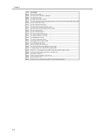
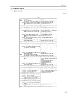
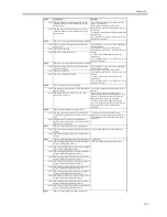
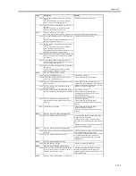
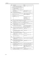
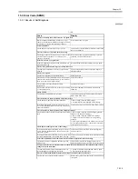
E602
the hard disk is faulty
E604
the image memory is faulty or inadequate
E609
the hard disk is faulty
E610
the HDD encryption key is faulty
E674
there is a fault in the communication between the fax controller PCB (2-line) and the main controller PCB
E710
the IPC initialization is faulty
E711
the IPC communication is faulty
E713
the communication with the finisher is faulty
E717
the communication with the NE controller is faulty
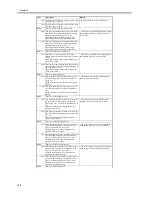
E719
the coin vendor is faulty
E730
the PDL software is faulty
E732
the reader communication is faulty
E733
the printer communication is faulty
E740
the Ethernet board is faulty
E743
the DDI communication is faulty
E744
the language file/boot ROM is faulty
E745
the TokenRing board is faulty
E746
the accessories board type is wrong
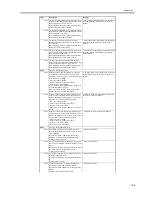
E748
the controller board and the SDRAM size do not match
E749
a change in the product composition has been detected
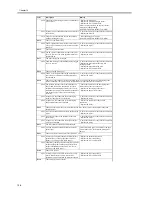
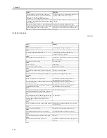
E804
there is a DC power supply fan error/there is an IH power supply cooling fan error
E805
there is a heat discharge fan error/there is a feed fan error
E821
the cleaner is clogged
E824
there is a primary charging cooling fan error
E840
there is a shutter error
E841
there is an error in the detection of fixing inlet guide solenoid connection
Code
Description
Summary of Contents for iR5570 Series
Page 1: ...Mar 29 2005 Service Manual iR6570 5570 Series ...
Page 2: ......
Page 6: ......
Page 26: ...Contents ...
Page 27: ...Chapter 1 Introduction ...
Page 28: ......
Page 30: ......
Page 55: ...Chapter 2 Installation ...
Page 56: ......
Page 58: ...Contents 2 9 3 Mounting the Cassette Heater 2 34 ...
Page 98: ......
Page 99: ...Chapter 3 Basic Operation ...
Page 100: ......
Page 102: ......
Page 110: ......
Page 111: ...Chapter 4 Main Controller ...
Page 112: ......
Page 114: ......
Page 135: ...Chapter 5 Original Exposure System ...
Page 136: ......
Page 181: ...Chapter 6 Laser Exposure ...
Page 182: ......
Page 184: ......
Page 192: ......
Page 193: ...Chapter 7 Image Formation ...
Page 194: ......
Page 198: ......
Page 259: ...Chapter 8 Pickup Feeding System ...
Page 260: ......
Page 350: ......
Page 351: ...Chapter 9 Fixing System ...
Page 352: ......
Page 401: ...Chapter 10 External and Controls ...
Page 402: ......
Page 406: ......
Page 448: ......
Page 449: ...Chapter 11 MEAP ...
Page 450: ......
Page 452: ......
Page 455: ...Chapter 12 Maintenance and Inspection ...
Page 456: ......
Page 458: ......
Page 468: ......
Page 469: ...Chapter 13 Standards and Adjustments ...
Page 470: ......
Page 505: ...Chapter 14 Correcting Faulty Images ...
Page 506: ......
Page 508: ......
Page 537: ...Chapter 15 Self Diagnosis ...
Page 538: ......
Page 540: ......
Page 565: ...Chapter 16 Service Mode ...
Page 566: ......
Page 568: ......
Page 633: ...Chapter 17 Upgrading ...
Page 634: ......
Page 636: ......
Page 641: ...Chapter 17 17 5 F 17 4 HDD Boot ROM Flash ROM System Software ...
Page 646: ...Chapter 17 17 10 F 17 11 8 Click START F 17 12 ...
Page 675: ...Chapter 17 17 39 F 17 59 2 Select the data to download F 17 60 3 Click Start ...
Page 677: ...Chapter 18 Service Tools ...
Page 678: ......
Page 680: ......
Page 683: ...Mar 29 2005 ...
Page 684: ......

